Single cell LVC and Shunt?

kokopelli314

100 mW
Joined
Oct 4, 2009
Messages
41
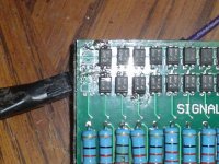
Ok so I've been riding a recumbent trike and a velomobile for exclusively for about 4 years. Car-free, by choice. Averaging between 12,000-15,000 km/year. Gone through lots of tires and replaced 5ah pouches in both Ping packs, 60/20 & 48/20. Also replaced the Signalab BMS in each. Even rode the 48/20 bareback for a month, while waiting for a BMS, never pulling more than 12ah. Been let down a couple times on 100+k rides. While pushing 120kg uphill at the lowest gear possible, with 30k left to pedal, I thought about all of the power, still in my 60v/20ah pack which kicked out at 15ah, just because of 1 pouch, in 1, 4 cell bank. Oy Vey, is this the best we can do??
So I thought about a single cell balance circuit that not only balance but would also shunt across cell banks that went below 2.2v. So the pack output would suddenly drop by 2.2v or so but would still be usable at say 46v, then 44 and so on. The drained cells would be isolated from the rest of the pack until the charger current reset, say a gate triggering a mosfet to reconnect the cellbank.
Does anyone know of a BMS like this? Seems to me that it would make far more sense than pedalling around a partially charged pack.
 
Not sure how to word my thoughts on this. or if I am understanding the question in the first place. So I will give it a stab anyhow. I think the goal is.

To eliminate the resistance of the weak cell group, to utilize all the capacity of the strong cells, to get you home, with the sacrifice of lower voltage.
Opinion is that you will further kill the weak cell group that is already comprised, by shunting. This may work if you can size the shunt value and cut in point, to prevent reverse charging.

Pete
 
The weakest cell group would be isolated by shunting across. In effect removing it from the pack. After some draw, the next weakest would be removed, and so on. LVC would be first, at cell level, then at perhaps at the controllers setting.
 
With enough wire and plugs, you could get that manually. But 16 plugs and wires sounds like a bitch. Ping packs do chop up into 12v sections very easily. That would be manageable.

So you could unplug a weak 12v section, and switch from a bms to a lvc buzzer on each section to limp home.
 
It's certainly possible, but the problem is you would need to electrically disconnect the low cell, as well as passing all of the current from the still-active cells through the bms circuit as well. It's a lot of complexity and cost for each cell, which is probably why it's not commonly done, if ever. Balancing circuits that shunt current during charge typically aren't shunting all the current of the charge, more often 10% or so. The more promising method is to actively (inductively) balance the pack once cells are in the 0-20% or so SOC range and move charge from the higher SOC cells to the lower ones. I believe that's exactly what the LTC3300 chips from Linear do. Lots of cost and complexity, but still possible.

Chopping into blocks as dogman suggested would be far simpler, not to mention cheaper.
 
any connection that bridges the cell will short it out. if you discharge the battery to the point one cell is at LVC then the entire battery needs charging in any case because there is not gonna be much charge left in the other cells. if you have one cell with capacity so far out it is time to replace it.
 
DAND214 said:
I think you are saying (Cell Group) not each cell in the group.

By bypassing the group you loose 3v of the pack.

Is that what you are trying to achieve?

Dan

Yes Dan, that is what I would like do. Simply and automatically remove cell banks that fall below2.2 v and run on the remaining cell banks at a reduced voltage. The bms would be used for charging purposes only. Not for shutting off a pack when a single 4cell bank or cell, whatever, reaches lvc
 
999zip999 said:
I think he would like to just cut out the one cell in the group. There's 64 cells in a 48v ping. Sounds like you need a 5c battery.

Yes Ive repaired my 60v and 48v already. Fortunately replacement cells are cheap. Considering individually bundling groups of 4, 5ah cells to make 20ah batteries that can be easily replaced
 
dnmun said:
any connection that bridges the cell will short it out.
The cell would be electrically isolated by lifting a terminal.
Repairing a Ping pack take an investment of time to unwrap, diagnose, unsolder and resolder, rebalance and rewrap. Not to mention the time required to purchase and ship.
I believe that this option is worth investigating
 
dmwahl said:
The more promising method is to actively (inductively) balance the pack once cells are in the 0-20% or so SOC range and move charge from the higher SOC cells to the lower ones. I believe that's exactly what the LTC3300 chips from Linear do.

Thanks for that. I checked out the ltc3300 specs and watched a video on the linear technologies site. Very interesting design concept, using neighboring cells to balance through mosfet controlled flybacks. I was wondering how this could be done. Wonder if theres another way? Capacitors and blocking diodes?
 
kokopelli314 said:
Thanks for that. I checked out the ltc3300 specs and watched a video on the linear technologies site. Very interesting design concept, using neighboring cells to balance through mosfet controlled flybacks. I was wondering how this could be done. Wonder if theres another way? Capacitors and blocking diodes?

I don't know exactly what you're talking about with blocking diodes, but it is technically possible using capacitors to shuttle charge back and forth. Problem is it's not too efficient and very slow. Capacitors charge at a rate inversely proportional to the voltage difference, so it turns out to not really be worth it. I built a quick circuit using an inverting charge pump (LM2663 if memory serves me) a few years back and tested it out, and it took days to see any difference between a couple 2ah cells. For what you want to do, it wouldn't be suitable though.

[EDIT] Capacitors charge at a rate proportional to the voltage difference, not inversely proportional. Not sure what I was thinking.
 
if you wanna just delete one cell in the series that is easy to do and you can hack the BMS down from 16S to 15S so it will still balance the pack.

i have a 14S pack i made from a 16S with the long 10Ah pouches, and i just hacked the BMS down to 14S and adjusted a 36V 2A ping charger brick up to 51V. works great.
 

Attachments

  • DSC01498.JPG
    DSC01498.JPG
    80.1 KB · Views: 1,906
That's a good hack. adjusting the charger and all. So bypassing the optoisolators prevents LVC from those groups from triggering pack shutdown?
 
dmwahl said:
I don't know exactly what you're talking about with blocking diodes, but it is technically possible using capacitors to shuttle charge back and forth. Problem is it's not too efficient and very slow. Capacitors charge at a rate inversely proportional to the voltage difference, so it turns out to not really be worth it. I built a quick circuit using an inverting charge pump (LM2663 if memory serves me) a few years back and tested it out, and it took days to see any difference between a couple 2ah cells. For what you want to do, it wouldn't be suitable though.

Just checked out http://en.wikipedia.org/wiki/Charge_pump and saw, pretty much what we"re talking about..i think.
Charge_pump%2C_2_stage.svg


So, it seems to me that as a bank is drained, by applying and releasing the throttle, the entire system could be "jiggled" so to speak into active balance. Is this making any sense?
 
yep, bypassing the two optos eliminates the LVC shut down. if you look closely you can see that the #16 optos were removed, the jumper starts on the upper side where the circuit current begins at the 14.75V from the top of cell #4.

my jumper bridges the two legs, from collector down to the emitter of channel #15 and there is a trace from the emitter on #15 to the collector on the top of #14. so that is how i bypassed the two upper channels.

this was done on the V1 siganalab. to do the same thing on the V2 signalab you do not have to jumper the HVC signal, only the LVC signal because ping changes the circuit design of the HVC signal. so you only have to put the jumper across the opto output for the LVC signal.

on the V2, the LVC signal is now on the inside row of optos. the outer row is the HVC signal. reverse of the v1 where the LVC is on the outer row.
 
Back
Top