
You are using an out of date browser. It may not display this or other websites correctly.
You should upgrade or use an alternative browser.
You should upgrade or use an alternative browser.
soldering vs spot welding debate
- Thread starter aethyr
- Start date
parabellum
1 MW
Or the other way around. If you decided to stress the cell with soldering, why would you need those tinny spot welds there? Flat solder connection of 6mm diameter has 28mm2 conducting cross-section. At this moment solder material or its thickness doe not mater any more.
geckocycles
1 W
Overclocker said:[youtube]0ZRwMXL-Rvs[/youtube]
here i applied the iron for LESS than 1 second. the joint is cool to the touch in 2 seconds.
spot welding only takes milliseconds. i got a video as well, shot at 400fps:
[youtube]gOUbVF2ef_o[/youtube]
spot welding definitely heats the cell a LOT LESS overall. but applies more intense heat on those 2 spots. but it's done at the bottom where the metal can is thicker so it's not a problem. try welding to the side to see what i mean
After you hit the batt with 3 welds the tab is way too hot to touch. After I solder with a 250W iron I can easily touch the tab after soldering. It takes a fraction of a second to solder. I adjust the temp to match the job. With this much mass, I get very consistent, quick solder joints. I first tin both parts. I will video with temp sensors and see for sure later. My 80w iron takes way too long. A thin solder joint isn't very strong compared to the spot weld but has more surface contact. Which is better, very little contact with spot welds or lots of contact with solder as long as the cell isn't damaged? I just don't see the current capacities of little spots. There are inconsistencies with solder. Sometimes it just doesn't stick well on nickle. Copper tabs are the way to go with solder IMHO.
tomjasz
1 GW
I just can't follow the logic. Wouldn't the industry solder if it were the better method, producing less heat? What m I missing, and I'm being sincere. Not snarky.
spinningmagnets
100 TW
Spot-welding is much faster and has a more consistent result, even when using minimally-trained personnel (low wages). Both are concerns for a mass-production business in manufacturing.
If a garage-builder is making one or two packs a year for themselves or a friend, a small amount of added time means that such a builder has several options they can choose from. Nothing wrong with the home-builder using a spot-welder, but...there are millions of home-builders who live in a country where the big battery manufacturers will not ship to them.
Some builders in this situation can barely afford to buy the components for a decent pack, and buying any kind of spot-welder is only a dream. If there is some way that techniques can be developed to allow a decent pack to be built using an affordable soldering iron, I want endless-sphere to be the place where the best info about this is available. (I have even seen large DIY soldering irons made from free junk)
I am now convinced that the negative end of the 18650 cells is the most sensitive to heat, and as a result, I believe that attaching a fuse-wire there is now the best course of action for the home-builder [if using solder], since connecting a fuse-wire requires less heat than connecting a 7mm X 0.25 ribbon. My research and personal experiments have shown me that the positive cathode-tip can take a lot of abuse from a spot-welder or soldering iron without any damage. [edit, see below. If using a spot-welder, there are benefits to adding fuse-wire to the positive end]
Plus, any heat that does develop on the negative end (due to a smaller current path through my suggested fuse-wire) will wick away and spread out onto the sides of the cell, where it is easier to shed (this is why Tesla does not use a PVC wrapper on the sides of their cells). Of course, the best pack design practices are to spec a cell and P-group sizes where the pack doesn't get hot in the first place.
spinningmagnets said:Spot-welding is much faster and has a more consistent result, even when using minimally-trained personnel (low wages). Both are concerns for a business in manufacturing.
If a garage-builder is making one or two packs a year for themselves or a friend, a small amount of added time means that such a builder has more viable options they can choose from. Nothing wrong with the home-builder using a spot-welder, but...there are millions of home-builders who live in a country where the big battery manufacturers will not ship to them.
Some builders in this situation can barely afford to buy the components for a decent pack, and buying any kind of spot-welder is only a dream. If there is some way that techniques can be developed to allow a decent pack to be built using an affordable soldering iron, I want endless-sphere to be the place where the best info about this is available. (I have even seen large DIY soldering irons made from free junk)
I am now convinced that the negative end of the 18650 cells is the most sensitive to heat, and as a result, I believe that attaching a fuse-wire there is now the best course of action for the home-builder, since connecting a fuse-wire requires less heat than connecting a 7mm X 0.25 ribbon. My research and personal experiments have shown me that the positive cathode-tip can take a lot of abuse from a spot-welder or soldering iron without any damage.
Plus, any heat that does develop on the negative end (due to a smaller current path through my suggested fuse-wire) will wick away and spread out onto the sides of the cell, where it us easier to shed (this is why Tesla does not use a PVC wrapper on the sides of their cells). Of course, the best pack design practices are to spec a cell and P-group sizes where the pack doesn't get hot in the first place.
Awesome take; while I certainly don't have the amount of experience in the field you do, my research goes into the same direction. Fuse wire on the - side; soldering on the +. Do you happen to have any build fotos of that configuration ? would love to see how it looks like before diving into it.
Just a thought:qwerkus said:Fuse wire on the - side; soldering on the +.
Since the whole can is -, if something dramatically physical (crushing, etc in a crash) happens to the pack causing shorts between cans, the fuses can do nothing to eliminate the short (they won't even see the current flow).
If they were fused on the + end, the same incident would break the circuits on each cell that was shorted.
That assumes that it isn't bad enough to actually crush the cells internally--at that point it doesn't matter much if things are fused or not.
")
Similarly, if a pressure was applied that caused a strip to short across the top of a cell from + to can, a fuse on the - side doesn't do anything, but a fuse on the + side would remove the short.
spinningmagnets
100 TW
Since the whole can is -, if something dramatically physical (crushing, etc in a crash) happens to the pack causing shorts between cans, the fuses can do nothing to eliminate the short (they won't even see the current flow)
That's a very good point. If a P-string is getting hot, and internal pressure building creates a breakdown internally in the weakest cell (with a manufacturing flaw?), leading to a thermal runaway, a fuse on either tip would be fine. In that case the rest of the cells in that P-string would be separated from the short.
When one cell shorts internally, it is as if that cell was replaced with a wire connecting the pos and neg busses on that P-string. Having individual cell fuses will not stop that single shorted cell from going off in a thermal runaway...its going up in heat and smoke, and there's nothing much to stop it but to take it outside and set it on concrete away from the house.
But...when that bad cells' fuse melts...it separates the other cells in that P-group from the shorted cell, to prevent the others from going into a catastrophic cascade, where severe heat causes one cell after another to go off...almost all at the same time.
There are two reasons I like the honeycomb layout, instead of a square rank-and-file. Both because doing that results in better air-circulation if the cells are spaced apart from each other about 2mm (or more). Of course you can space out the cells in a square pack, but once you draw it out life-size on paper, I am convinced that honeycomb is slightly better.
Some air-space and air-circulation between the cells allows the option of an added air-fan (I recommend two, one pulling, one pushing, centrifugal 48V DC server fans with ball-bearings...very cheap and long-lasting). But...even if an air-fan is not added, if you construct two almost identical packs (both honeycomb) but one has all the cells touching to make it compact, and the other has a 2mm air-space between each cell?...
Hard running will make the pack warm, but the cells near the edges can shed some of that heat. The center of the pack will remain the warmest part. If there is a heat-related cell-failure, it is likely to be in the middle of the pack. If all the cells are touching (to make the pack as compact as possible) it will be very bad. If they each have just a little air-space...it will be..."less bad?"
First, make the pack large enough that the P-groups are not strained. Second, chose a cell that can handle the loads you will be applying so it only gets a little warm at the worst. Third, If the center 30% of cells in a pack die an early death due to frequently running warmer than the cells at the edges, will you rebuild this two-year old pack? NO...you throw away the entire pack, so...getting the heat out of the center of the pack can double the life of a pack.
Tesla has an eight-year warranty on their battery packs, and a 2-year old Tesla-S taxi just passed 300,000 miles while the pack is still providing over 90% of its rated range when it was new. They are doing something right.
Tesla NEEDS individual fuses because...they have over 70 cells per P-group. If one cell internally shorts, then all 70 of its neighbors will instantly be dead-shorting too, through that shorted cell (acting as a solid wire during a short).
If you have a spot-welder, I now agree with amberwolf. You should spot-weld the fuse-wire onto the positive tip, and spot-weld bus-ribbon to the negative. This provides better protection in a crash scenario.
However, if you will be using a soldering system (and hundreds in the third world will be), I would still connect the fuse-wire onto the negative, to prevent even coming close to heat-damaging the internals. If you overheat the plastic separators inside the cell, they will shrivel up and expose the parts they were designed to insulate. You could be creating the very scenario that you are hoping the fuses will avoid.
My goal is not to get people to solder instead of spot-weld...my goal is to help those who are limited to soldering, by identifying the methods and materials that will make a soldered pack as safe as it possibly can be. I am open to hearing persuasive suggestions to the contrary on any point.
"Fuse-wire for individual cells, DIY Tesla style"
https://endless-sphere.com/forums/viewtopic.php?f=14&t=88039
spot-welded steel fuse-wire
If using a soldering connection, fuse-wire can be copper or aluminum (if desired)
qwerkus said:Do you happen to have any build fotos of that configuration ? would love to see how it looks like before diving into it.
Take a look on this:
https://endless-sphere.com/forums/viewtopic.php?f=14&t=88039#p1286723
T.
geckocycles
1 W
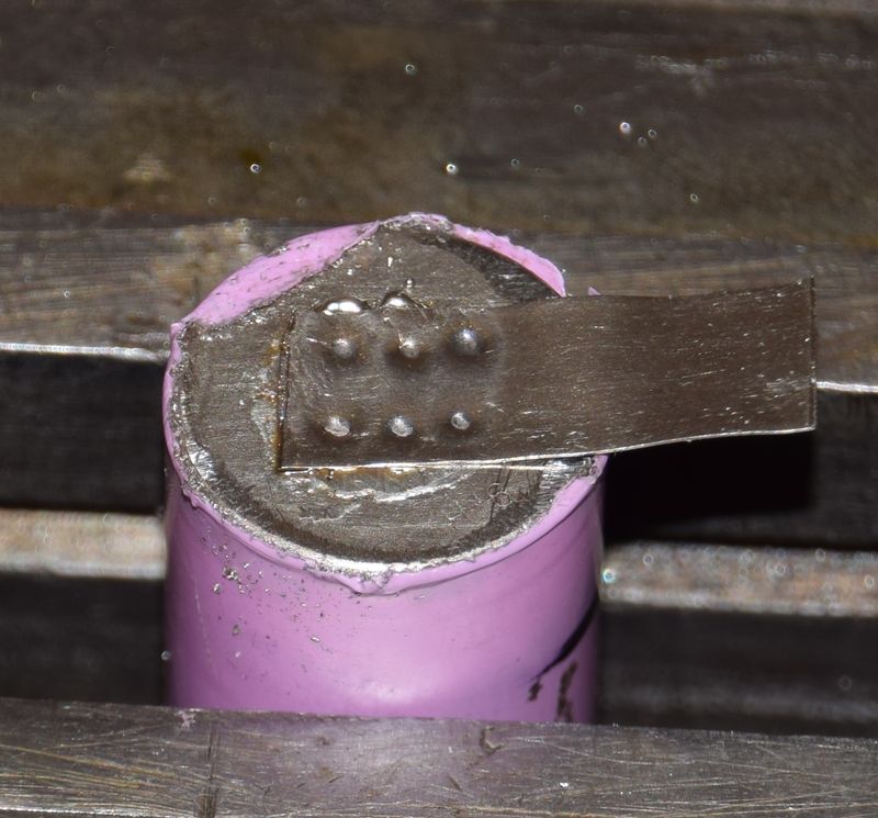
I just stuck some .15mm nickle to - side of several batteries.
Tinning battery takes .8 sec and leaves too much solder. I can touch with my finger as soon as I put the iron down. TInned nickle and soldered it to battery. 1.5 sec. Can touch only for a couple of seconds. Measures 165F on battery bottom. The tab get much hotter.
I did 3 welds with the Arduino with clean tips at 60MS which was too high and temp was 99F. When I pulled the tab off it put a hole in the - side and vented just a bit. THe battery had no voltage in it to begin with. So 3 hits set too hot is still cooler than a very fast solder.
So I would say, even with this 250w iron set at 400F and minimal time it still heats up the cell more than spot welding but I don't think it is very much difference to hurt the cell. The issue is when you leave an iron on the cell for longer than a second or so with a less powerfull iron. I cold modify the tip to better suit this particular need and I bet that would help immensely. More like the flat grind in the solder in less than a second video. This one is a bit too wide.
I tried smashing thin solder to just a film and put it between battery and tab. Used spot welder set at 50. It solders to tab and battery but spot weld is not going through solder to battery enough on first hit. Two more hits and it worked well. Peeled tab off and it left tab material on battery and you can see film of solder on both parts. Thin solder alone may have more contact but I can pull the tab off much easier than a welded tab. Still solder may not be as strong but it has more surface contact than a spot. Soldering is very fast though using the spot welder. I even tried just rolling up some .032" dia solder and placing the circle under tab. THe first weld pushes down the tab through solder and next welds to battery better. When I pulled the tab off, the tab tore at several welds and tore in half. Lots of solder on both parts. I put a small amount of flux on the tab, none on the battery. I wipe with alcohol.
spinningmagnets
100 TW
Since the nickel ribbon is stiff and flat, the area around the 'spot weld" is still pressed against the cell end enough that there is a much greater conductivity patch than is at first obvious. If there was a significantly tiny-enough connection for all of the current, it would show up as heat on a thermal camera.
I agree that the spot-welded connections (Typically four spots) are smaller in area that a broad soldered connection, but...solder is a poor conductor, worse than nickel.
100/100 Copper (IACS)
24/100 Nickel
12/100 solder 60/40
I agree that the spot-welded connections (Typically four spots) are smaller in area that a broad soldered connection, but...solder is a poor conductor, worse than nickel.
100/100 Copper (IACS)
24/100 Nickel
12/100 solder 60/40
Since the path length from the cell to the strip is extremely short, I don't think there would be a noticeable difference between the welded vs. soldered. Most of the resistance will be somewhere else.
I figured if the combined surface area of the welds was more than the cross sectional area of the nickel strip, it should not be a bottleneck.
I figured if the combined surface area of the welds was more than the cross sectional area of the nickel strip, it should not be a bottleneck.
llile
1 kW
- Joined
- Dec 18, 2010
- Messages
- 457
While I'm waiting for the high current Vruzends to come out, I'm sitting here stopped on my battery build. I could totally build a battery using soldering, but I've been reluctant. This fuse wire idea is great! Small wire means fast soldering. Happened to have some bad 18650's laying about, and found with my trusty Hakko 65 W temp controlled iron, and a fatty tip, I could solder a 26 gauge wire ( 0.025" dia ~ 40 amp fuse wire https://www.powerstream.com/wire-fusing-currents.htm) in the count of one-two-three using fine rosin core solder. Touch it as soon as the solder is hard, and it isn't hot. Sometimes I needed two tries, but mostly got it in one after a little practice. Why not use a big giant 250 watt prod and a roll of solder as thick as a pencil? The Hakko is surprisingly fast, and with a ball of melted solder on the end of the biggest tip, has a surprising amount of mass, but it the temperature isn't excessive. A 30 gauge (0.010" dia, about a 10 amp fuse) takes the same, but darn that's a really small fragile wire.
[Yet Another EDIT] I can solder 6 gauge copper with the Hakko, gotta scrub it a little, but it works fine. I'm leaving that 250-watter out in the garage with the plumbing stuff.
I wonder what happens if you short one of these batteries with a 40 amp wire on it? Am I stupid enough to find out? Probably am. If I do this it'll be outside, with a face shield, and the battery will be inside a concrete box. :lol:
I'm pretty skilled at soldering, and this may give me the confidence to dispense with waiting on high current Vruzends, and just try building a pack the old fashioned way. I can't imagine such a brief amount of heat would cook the batteries.
[EDIT] tried it with a junk 18650 cell, 30 gauge (approx 10 amp fuse wire ) and a very un-dramatic spark let all the magic smoke out of the wire instantly. Charged battery still at 4.22 volts at the end, and it accepted 10maH of charge.
[EDIT] tried a 26 gauge fuse wire (0.0254" dia, ~ 40A). The wire became red hot but did not fuse, the battery became hot. battery at 4.08 volts at the end, still mostly charged. Wire was smoking hot for 15 seconds, red hot for 5 seconds but did not burn out. At that point I chickened out. Clearly 26 gauge is too heavy, and 30 gauge is probably too light just because it is fragile. 22 gauge might be just about right, theoretically a 20 amp wire. I have no way to accurately gauge the current flowing here.
[EDIT] Tried shorting out a 24 gauge fuse wire in the positive, and a 26 gauge wire on the negative. This seemed really ideal. The 24 ga (0.020" dia, roughly 30 amp) turned red immediately and parted in about the count of three, a nice time delay but not too long. Battery was still at 4.05 volts at the end of these tests, so there wasn't that much actual energy involved, just a lot of power. No way 30 amps is any kind of normal current for my rig, it should be more like 3 amps per cell. At 2 amps (as high as I can test accurately with my bench power supply) niether wire gets at all warm. Resistance of an inch of 24 gauge wire should be 2 milli-ohms theoretically, not enough to add any significant resistance to the pack or even a cell. I think I will order a roll of 24 gauge tinned copper wire.
Wow, great test results. Thanks for trying it out. I'd love to see video
I've seen some packs where they used a pair of small wires. You could take a piece and bend it into a U shape with a small radius and solder at the bend. Not sure what happens when a pair of wires wants to fuse. For sure you don't want it to just glow red for a long time. At the normal current max, it should not be getting too warm.
I've seen some packs where they used a pair of small wires. You could take a piece and bend it into a U shape with a small radius and solder at the bend. Not sure what happens when a pair of wires wants to fuse. For sure you don't want it to just glow red for a long time. At the normal current max, it should not be getting too warm.
bobmutch
100 W
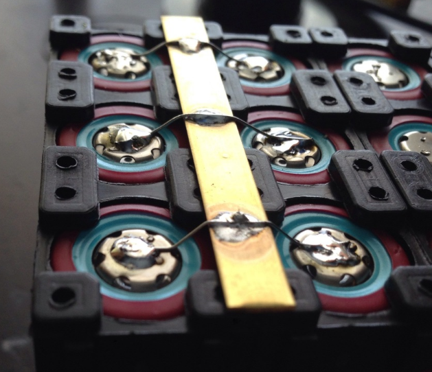
3 second solder job

Should do one one weld at a time as you go down the line and then come back and do the 2nd weld then come back do the 3rd weld.

The worse I could find on the video

Like this, one weld at a time.

Video where you can see all this.
THERMAL CAMERA Imaging of Soldering Vs Spot-Welding 18650 cells
https://www.youtube.com/watch?v=byvr-dwwao4
Should do one one weld at a time as you go down the line and then come back and do the 2nd weld then come back do the 3rd weld.
The worse I could find on the video
Like this, one weld at a time.
Video where you can see all this.
THERMAL CAMERA Imaging of Soldering Vs Spot-Welding 18650 cells
https://www.youtube.com/watch?v=byvr-dwwao4
liveforphysics
100 TW
This thread topic could be re-phrased as, is it better to hit yourself in the balls with a baseball bat, or a golf club?
Firstly, using FLIR on shiny nickel surfaces is laughable, because it's something like 5-10% emmisitivty, so those temp values it's reading are +->100degC of being useful for something.
Lastly, the temp on the top of the nickel is utterly irrelevant, as the top of the nickel isn't the heat sensitive area.
When you solder a can, and then cut the cell apart, you will see the seperator layer is melted together and deformed on the ends, and the can has excessive gas pressure, and the thermal decompoisition breakdown products of the carbonate esters in the electrolyte are going to cause it to age poorly and develop self-discharge from the impurities released by that thermal breakdown.
When you spot weld a can, it's not the upper side that matters at all. Not even relevant to talk about or look at or consider. When you cut that cell apart, and you see the underside of the can which was glowing red hot steel (2500degF) for the weld to be possible, you see the internal corrosion resistant surface lining of the can is vaporized away, and in it's place is carbon debris from flash boiling electrolyte carbonates, and now that carbon will be polluting your cell to increase self-discharge rates.
If you're going to try to spot weld, you don't do it based on how the welds look externally, or how hard they are to pull off the can, those metrics are childs play to nail and just don't matter with respect to making a pack that will last. You must tune the process by cutting open the bottom of each cell you bonded to and examening the damage to the end of the jellyroll, and examen the bottom of the can surface for what kinds of thermal decomposition products are now poisoning your otherwise very pure electrolyte.
Soldering packs is for applications where you don't care if it even works once, random self-discharge levels are acceptable, and random failure in a short time is desired.
Spot welding (to the bottoms of cans) is for when you don't care about leaking electrolyte out of the can from the stress risers in the heat-effected zone near the weld fusion site (where it was 2500degF), don't care about having the corrosion resistance can coatings remaining functional, and want to pollute your electrolyte with random carbon debris (think setting your breakfast in a frying pan at 2500degF).
spinningmagnets
100 TW
That's a very persuasive argument!...
Thanks for the detailed explanation Luke.
But if the heat affected area of the welds is small, the amount of contamination and damage will also be small. Spot welding of 18650s is the standard procedure used in millions of laptop batteries and their track record is not so bad. Even medical batteries used for life support equipment are still spot welded. Maybe we don't know how much better the packs would last since nobody makes them with a better process (at least not that I've seen). With a pouch or prismatic, at least you can make a welded connection that does not affect the chemistry.
But if the heat affected area of the welds is small, the amount of contamination and damage will also be small. Spot welding of 18650s is the standard procedure used in millions of laptop batteries and their track record is not so bad. Even medical batteries used for life support equipment are still spot welded. Maybe we don't know how much better the packs would last since nobody makes them with a better process (at least not that I've seen). With a pouch or prismatic, at least you can make a welded connection that does not affect the chemistry.
shaman
1 kW
liveforphysics said:Soldering packs is for applications where you don't care if it even works once, random self-discharge levels are acceptable, and random failure in a short time is desired.
Spot welding (to the bottoms of cans) is for when you don't care about leaking electrolyte out of the can from the stress risers in the heat-effected zone near the weld fusion site (where it was 2500degF), don't care about having the corrosion resistance can coatings remaining functional, and want to pollute your electrolyte with random carbon debris (think setting your breakfast in a frying pan at 2500degF).
This being said, @liveforphysics what is the ideal method for stringing cells together for a pack? Is there a good alternative to spot welding and soldering?
liveforphysics
100 TW
shaman said:liveforphysics said:Soldering packs is for applications where you don't care if it even works once, random self-discharge levels are acceptable, and random failure in a short time is desired.
Spot welding (to the bottoms of cans) is for when you don't care about leaking electrolyte out of the can from the stress risers in the heat-effected zone near the weld fusion site (where it was 2500degF), don't care about having the corrosion resistance can coatings remaining functional, and want to pollute your electrolyte with random carbon debris (think setting your breakfast in a frying pan at 2500degF).
This being said, @liveforphysics what is the ideal method for stringing cells together for a pack? Is there a good alternative to spot welding and soldering?
Ultrasonic is the best method if you need to weld. If you're a DIY'er who's not willing to invest in a DIY ultrasonic welding setup (which is more complex than most folks DIY skills), use a solder-less weld-less pressure interconnect system. We have many examples of good designs and terrible designs at accomplishing cell pressure interconnects.
Similar threads
- Replies
- 26
- Views
- 7,250
- Replies
- 9
- Views
- 9,104