igashosparks said:
I love the idea of the wattmeter between battery and controller... looking at the wiring diagram on Amazon, is that shunt exposed circuitry? or do you insulate around the shunt as needed?
The best way is to bolt it to a mounting spot on the frame, ensuring it is insulated from the frame. Then it can't float around and wear thru whatever insulation is used, if it happens to bang or rub on something.
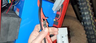
Otherwise, you can just do it the same way the fuse is installed (except it goes in the *negative* battery lead instead of positive), and insulate it however you need to.
BTW, I recommend the heatshrink insulation rather than electrical tape, mostly because tape tends to unwrap itself over time as heat/humidity/etc degrade the adhesive. Some tapes are better than others (like the 3M brand stuff usually works better than most generics, and there are automotive grades intended for more abusive environments, etc).
If using heatshrink I would get the thickwall stuff, so when shrunk it will better protect. Or use two or three layers of thinner stuff. HS usually shrinks to half or less of the original diameter, so get a size that will easily slip over everything involved. If the wires to the items are way smaller than the items, you might need two sizes to make a water-intrusion-resistant covering, but if you only need to make sure the contacts of things cant' touch anything else, just the one size should work fine. (meaning, all the fusing / wiring / etc you're working with is inside a box or other already-water-resistant containment).
Just cut a couple inches longer than you need to entirely cover the entire fuse and bolt connections including the crimped areas of the wiring lugs, slip the HS over the wiring with the fuse (or shunt) unbolted, then bolt down and slide one layer of HS over the area to be protected. Heat just that piece till it's fully shrunk, but not enough to melt it, and wait for it to cool. Then do the same with any additional layers.
If you need to see the fuse window, you can just cut a small hole in the covering HS at that point; it wont' expose the conductors so would be fine as long as you're not looking for waterproofing there.
If you need better waterproofing, you can get adhesive lined marine-grade HS so it sticks to the wires/etc to better resist intrusion.
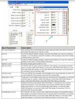
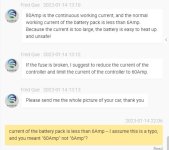
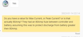
Regarding limiting the controller to 40Amps, or some other number below the max of 80.. I guess I can play around with it, and either leave it at 80-Amps for the hill climbs, or find a happy medium that provides enough power to get the job done..
Experimentation is usually the most certain way, but I do recommend the wattmeter to be sure what power draw you are actually getting in various use-cases.
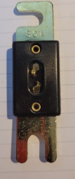
Regarding the fuse itself: after some research on the manufacturer site, this spec sheet from Eaton for Bussman ANL fuses says that the series has versions that are good for up to 80v maximum:
https://www.eaton.com/content/dam/eaton/products/electrical-circuit-protection/fuses/bussmann-series-supplemental-fuses/supplemental-fuses-limiters/bus-ele-ds-2024-anl.pdf
View attachment bus-ele-ds-2024-anl[1].pdf
Specifications:
Ratings
• Volts 80Vdc or less
• Amps 35-750A
• IR 2700A
So they should be safe to use with your system voltage, and still properly disconnect under load.
Interestingly, the chart on the second page
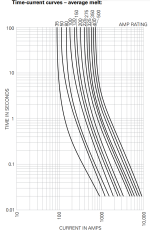
says that for this specific model, with an 80A version of the fuse, it will take about 150A to blow within about 100 seconds (a minute and a half). This is an "average" time, and they dont' state the range of min/max that is derived from, so some fuses could take a lot longer or shorter time to blow at any specific current...but I would guess from the chart that they should still all sustain under 80A indefinitely. The chart is exponentially drawn, so it's difficult to see exactly where the curve is intersecting when not near a line. Just a little bit more current than that would blow it in a tenth of that time. Twice that current would blow it in just a second or so.
A short circuit (like say, touching the positive and negative together, or a controller failure of FETs blown such that they short these) would probably draw many times that current, and so blow in an exponentially shorter time.
So....assuming the controller can be persuaded not to draw more current than the battery itself can take (the 80A it's marked as) you can probably continue to use the 80A version of this fuse, assuming that the manufacturer of the specific fuse you have followed the Bussman specifications, if they are not Eaton/Bussman-manufactured. If they didn't make them identically to those (fuse-metal alloy, size, shape, etc), then it would require the chart from that specific manufacturer, or experimentation, to find the actual limits of that specific fuse.
I have an all terrain electric skateboard that has this... on the throttle/remote you can set it to 4 different levels in increments of 25% of full power.. Level 4 it goes 35MPH on flat paved ground which is pretty insane on a skateboard, but off road and up hills the extra power comes in handy. Something like that would be useful on the bike, but no.. I don't believe my controller/display has this feature.
If the controller has a "3-gear" or "3-speed" switch input, usually just two wires and a ground, then if the programming software for it can change that to control the battery current limit vs the speed limit, or if the throttle percentage that it likely switches can be used to control the current limit (meaning a "torque" or "current" throttle rather than a "speed" or "PWM" throttle), then that can be wired to a switch like those used for turn signals with on-off-on contacts on the back, to give you three presets: whatever is setup in the programming software.
If it can only change the speed limit, it won't do what you need it to for the current limiting.
I'll see what I can find on how it does what it does if it has a 3-speed input. Is yours a V1 or V2? If it doesn't say, it's probably a V1. (just in case their functionality is different)





![Battery%20Front%20Sticker[1].translated.jpg Battery%20Front%20Sticker[1].translated.jpg](https://endless-sphere.com/sphere/data/attachments/189/189894-2dee3fc2ee6c551faf4f09b6143cd690.jpg)

