
• Hello ES! We could use some help to get us past the finish line on building the new knowledgebase for the forum.
    Can you donate? Please see our fundraising page. Thank you!

SOLVED : CA3 does not get Speed from PhaseRunner

Raphael303

New-ish here
Joined
May 31, 2016
Messages
38
Hi

I have bought a new PhaseRunner (WP8 and L1019), hooked it up, Autotuned it in the software suite, setup works normal, but the CA3 does not get the Speedometer signal from it. Speed shows 0 at all times.

My CA3 has a retrofitted WP8-Plug, so I tripple checked the wiring right down to the "SP" Pad in the PCB of the CA3 (I opened it). It is definitly hooked up correctly, the speed signal goes where it has to go on the WP8 plug. Also quadruple checked that I'm not looking at the plug mirrored.

When I measure the voltage on the SP Pad I get 0 Volt. When I turn the wheel by hand I get nothing either. When I use the throttle to spin the wheel I get a continuous voltage proportional to throttle. Since the wheel is spinning freely I couldn't test it too much, but it never went up to 1V.

In the PhaseRunner suite I can see the RPM displayed live. It is set to Hall-Sensor mode. The motor is a Crystalyte Crown TC3080. I can spin the motor with throttle and it also reacts to torque input while riding the bike, however with far too little power. Which could be related to the CA3 not reading any rpm and speed.

I have attached my settings files to this post.
I connected and checked wiring according to the pix bellow.

Any help is appreciated.

CA_Pad_Layout.gif

WP8-Pinout.jpg


SOLVED


The white wire "speedometer signal" that goes to the Phaserunner/Baserunner L1019 plug need to be paralleled with one of the hall signals if your motor does not provide a speedometer signal.

The hall signals alone are not enough. Even though the PR/BR know the speed, they will not send it to the CA3, also not if you set "HDQ replicating HALL" in the custom parameters. The speed signal that goes to the CA3 from the PR/BR is the speedsignal that goes TO the PR/BR. So you need to provide this.
 

Attachments

  • PR and CA3 Settings.zip
    2.6 KB · Views: 94
Update, I have, in parallel, converted my wife's bicycle to electric.
For her I bought a new CA3 with the MF-Switch and WP8-plug and a baserunner with L10 and WP8. The only thing I modified here is, that I attached a L1019 Plug to the motor.

I autotuned the baserunner with the software, all worked well on first try. BUT:

Hers does not show speed in the CA3 either.

So bottom line I have two bicycles with CA3 and base/phaserunner whose CA3s do not get speedometer from the controller.

This must be something I set up wrong. No?
 
If you get no signal at the SP pad in the CA, then there's a wiring issue.

If you are not using the CA version that comes iwth an external speedometer you mount on the frame or fork and a magnet on the wheel, then the CA must get the speed signal from one of the three hall sensor signals from the motor.

So since you're not getting the speed signal at the CA itself, but you are getting the halls to read correctly in the setup software, (meaning the controller can see them from the motor), it means that most likely the SP wire between the CA and the controller is not connected, somewhere along it's length.

This statement:
Raphael303 said:
When I measure the voltage on the SP Pad I get 0 Volt. When I turn the wheel by hand I get nothing either. When I use the throttle to spin the wheel I get a continuous voltage proportional to throttle. Since the wheel is spinning freely I couldn't test it too much, but it never went up to 1V.
sounds like there is a miswire; if you mean that you get a voltage that "ghosts" the throttle voltage but not at the same voltage range.

You should be getting pulses on the SP pad, one for every time a magnet passes whatever sensor is connected to it. If there are no pulses on the SP pad, *but* the pulses *are* being read by the controller, the pulses are not making it from the controller to the CA.


There's no setting in the CA itself that I know of to change where it gets the signal, only how many poles (pole pairs) the magnet setup driving the sensor has. On a typical DD hubmotor, that's 23, but you'd need to check your specific motor for that info. For an external sensor on the frame with magnet on wheel, that's 1.

I don't know if the PR or BR has to have an output enabled to send a speed signal or not, but it would seem odd to me if it did (most controllers simply wire the CA-DP plug so the Speedo wire goes directly to one of the hall sensor lines coming from the motor).
 
Hey Amberwolf, thank you for your response and your time.

Even though I checked the wires already many times I just went back and checked the L10 connector which I wired to both of the bikes, since this is the only common thing on both bikes. Doing measurements there is not simple, but I checked if all the hall sensors have the same resistance to Gnd/5V and thus are on the correct pins. They all read the same values in the MegaOhms to 5V and something in the kOhms to GND. I also started up the Phaserunner suite again, looked at the dashboard and can clearly see all HallSensors light up. I can print a graph with RPM and Speed there. No Problem. With both bicycles.

So, as you point out, the problem SHOULD be in the wiring from the PR/BR to the CA3s. However, I did not to anything to the wiring from the BR to the CA3-WP, since they both come with the 8 pin WP plug and I only connected the stock cable.

I believe at least for the bicycle with the baserunner I can rule out any wiring problems, since I see Hall, Speed, RPM in the phaserunner suite.
 
Well, unless the PR is internally not passing the hall sensor signal from the motor to the CA connector, either in hardware or software, then the problem must be wiring between the PR's speedo output pin and the CA's speedo input pad on the PCB, if there is no pulsing signal at that pad.

If the version of the PR you have uses the WP8 connector as listed here
https://www.ebikes.ca/product-info/phaserunner.html#cables-and-connectors
then pin 2 of that is the speed output. If there is no speed output signal at that pin, then the problem is within the PR itself somewhere, or that cable stub.

If there is a speed output signal at that pin, then the problem is in the cable between the CA's PCB and that connector.

I couldnt' find anything specifically on the page that says where that WP8 pin 2 actually goes inside the PR, but this is listed on that page about the 2-pin JST temperature/speed connector.

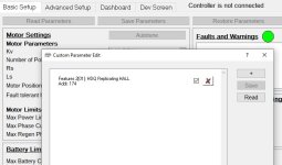
Speed/Thermistor Pass Thru - JST-SM: The extra 2 pin female JST-SM plug is present in order to hook up additional inputs to the WP8 Cycle Analyst plug. If the motor has a built in temperature sensor, this signal can be fed to JST Pin1 to show motor temp on the CA3 and enable thermal rollback. Geared motors that have an internal speed sensor should use Pin2 as a pass-thru of the speedometer signal line to get speed display on the CA3. In this case, the setting at address 174 "HDQ Replicating Hall" should be unchecked. For direct drive motors, the motor speed will go through automatically to the CA3 as long as "HDQ Replicating Hall" is selected.
"HDQ Replicating Hall" on that page is a link to this image:
HDQ_On_Hall.jpg
but I don't know where you access that.


The unlikely possibility exists that in this version, for whatever reason, there may be no connection between any of the hall sensor inputs and the WP8 pin 2, and *instead* that pin may only be connected to the 2-pin JST that is for temperature and speed sensor input from the motor. If this is the case, then you would have to connect a wire from the motor hall JST connector, from any single hall signal, to the 2-pin JST's speed sensor pin. Based on the quote above, I don't think this is the case, but brougth it up as an option if there is no other solution. I don't know what effect it might have on the PR's operation to do this.
 
Thank you.

I have checked pin 2 directly from the controller of the PR on the WP-8 Plug. there is nothing.

I also tried the setting you posted above (it's in the menu - edit - edit parameters) it didn't work either.

Also it still puzzles me that two bikes do it. One with PR and one with BR...

I think I'm gonna call Grin Tech today, since they don't respond to my email.
 
If there's nothing on the PR's Speedo output wire, but it is getting all the hall signals, and the setting to replicate hall to speedo is on, then I can't think of anything else it could be other than a wiring fault inside the PR itself or the cable to the Speedo wire (presumably molded into the PR).

But Grin should be able to figure it out, if anyone can.
 
amberwolf said:
If there's nothing on the PR's Speedo output wire, but it is getting all the hall signals, and the setting to replicate hall to speedo is on, then I can't think of anything else it could be other than a wiring fault inside the PR itself or the cable to the Speedo wire (presumably molded into the PR).

But Grin should be able to figure it out, if anyone can.

It's my opinion too, but still, a Baserunner and a Phaserunner with the same problem... still seems odd. AND, Grin is ignoring my emails and, as for their website, don't want to be called, but only emailed....
 
Just as an update also in case Grin has a look at this forum. I'm still stuck and my email(s) to grin remain un-answered since the beginning of the week.
 
SOLVED


The white wire "speedometer signal" that goes to the Phaserunner/Baserunner L1019 plug need to be paralleled with one of the hall signals if your motor does not provide a speedometer signal.

The hall signals alone are not enough. Even though the PR/BR know the speed, they will not send it to the CA3, also not if you set "HDQ replicating HALL" in the custom parameters. The speed signal that goes to the CA3 from the PR/BR is the speedsignal that goes TO the PR/BR. So you need to provide this.
 
I know this is an old thread and I'm sorry to open an old can of worms...BUT...my Phaserunner MT/CA3 is doing exactly the same thing. I have a QS205 hooked into a Phaserunner MT then a CA3. It works great but no speed measurement. The QS205 has a white wire that is with the other usual hall signal wires that I assumed is the speed wire. I hooked it up to the speed wire on the 3 pin JST per the manual and nothing on the CA. I unhooked it as the manual says a direct drive can use the hall signals...nothing. I made sure the "HDQ" was checked...nothing. I unchecked it...nothing. I hooked up another CA3...nothing. The above "Solved" explaination is confusing to me. I have a Phaserunner MT not sure how to get the speed going. I have two other geared drives that work great. Not this setup......
 
QS205 doesnt' have a speed sensor, just a thermal sensor.

If you want a separate speed sensor from the halls in it, you'll have to install a frame-mounted one and put a magnet somewhere on the wheel.

If it doesnt' read the motor halls, even with the PR's speed senosr input wire paralleled with one of hte motor hall sensor signal wires, then I don't know what else it could be.

you can verify the PR's speed sensor input is working by rapidly switching it from 5v to ground, and watching the setup program's monitor of the sensor to see if its' detecting the activity.

You can verify the CA's speed sensor input the same way.

If both of those are working, then connect hte CA's speed sensor input ot the PR's speed sensor output, and then test the PR's speed sensor input as above, and you should see the output on both the CA and the PR.

Note that at least some versions of the PR automaticlaly use the motor hall sensor input for speed if they don't receive a signal from the speed sensor input for a certain amount of time, but it *does not* divide that down by the number of poles in the motor to equal the number of poles you had set for the speed sensor, and so it then outputs a way too fast speed signal to the CA, as well as potentially engaging any speed or RPM limiting you've setup within the PR itself.
 
You said, “even with the PR's speed senosr input wire paralleled with one of hte motor hall sensor signal wires, then I don't know what else it could be.” How do I do that? Hook a motor sensor hall into the speed input? Thanks so much for your help!
 
Last edited:
I’ve read this thread and your response over and I think I get it. The CA gets it’s input from that PR speed input pin not from the halls themselves so a hall is jumped/paralleled to that pin giving it what it needs to go to the CA….hope i got it right!
 
Yeeeeee Haaaaaa.....got it! Ran a jumper from one of the halls to the Phaserunner MT speed pin and BAM....it works great. Thanks for the help! Grin needs to put a page in the manual about it...for 350 bucks I think one paragraph is not going to kill them...just sayin.
 
Yeeeeee Haaaaaa.....got it! Ran a jumper from one of the halls to the Phaserunner MT speed pin and BAM....it works great. Thanks for the help! Grin needs to put a page in the manual about it...for 350 bucks I think one paragraph is not going to kill them...just sayin.
I have the same issue and same controller Could you explain what you did you solve it what did you buy?
 
I have the same issue and same controller Could you explain what you did you solve it what did you buy?
I had the same issue in my installation with Phaserunner MT V6 and a QS motor. The solution described in the thread worked for me, you branch out any of the three hall sensor signal wires and feed it into the speed sensor input of the controller.

I have my wiring hidden in a box I can't take a pic for you, but you just go off the phaserunner manual. In my installation I branched off a blue hall from the provided anderson MT cable, and run a wire to pin 3 (wheel speed) of the three pin phaserunner connector. In your pic you show a middle pin connected, maybe that's the problem and you are feeding the signal into the thermistor input?
Screenshot_20260711-221212 (1).jpg
 
I had the same issue in my installation with Phaserunner MT V6 and a QS motor. The solution described in the thread worked for me, you branch out any of the three hall sensor signal wires and feed it into the speed sensor input of the controller.

I have my wiring hidden in a box I can't take a pic for you, but you just go off the phaserunner manual. In my installation I branched off a blue hall from the provided anderson MT cable, and run a wire to pin 3 (wheel speed) of the three pin phaserunner connector. In your pic you show a middle pin connected, maybe that's the problem and you are feeding the signal into the thermistor input?
View attachment 390392
Can you see my photo? I did this to the yellow wire, but no efffect, still error code 30 and no pedal asssit.
 
Last edited:
Back
Top