spark resistor help

zypher

1 W
Joined
Oct 6, 2012
Messages
53
Location
New Jersey, USA
I am planning on adding a anti-spark resistor where the battery connects up to the controller. I found the calculator online http://scriptasylum.com/rc_speed/nospark.html (see pic below). Where it says "Enter total battery voltage" I used the 16s from the drop down menu. I don't use Lipo, I have Lifepo4 48v 15ah, I guess it doesn't matter. Next I choose 2 Seconds for the "charge time". Finally, In the "Total ESC Capacitance" I left the uf at 1000 as I don't have that info and the (?) info window said that that is a pretty common value. I believe the resistor I am looking for is 400 ohms / 8.762 watts rounded up to 9 watts or rounded down the 8 watts, don't know which is better. Does this sound right to you guys...Thanks for your help.
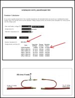
zzzzzu.jpg
 
in that picture there is an exposed metal cap that the resistor supposed to touch. that metal cap is a fire hazard. it can short the battery to ground and cause a fire.

you don't need a 9 watt power resistor. anything in the 100-1000 ohm range will work and even a 1/2W will be ok since it is only milliseconds of hi current.
 
dnmun said:
in that picture there is an exposed metal cap that the resistor supposed to touch. that metal cap is a fire hazard. it can short the battery to ground and cause a fire.

you don't need a 9 watt power resistor. anything in the 100-1000 ohm range will work and even a 1/2W will be ok since it is only milliseconds of hi current.

That's just a picture that I found online. The shrink wrap was left out for clarity. Thanks for your help.
zzzzzw123.jpg
 
This will work with any battery up to about 150V. I used 150 ohm 10w resistor. Don't use anything higher than 180 ohm for good results across all voltages and cap sizes to charge. I still got a big spark at 270 ohm with my controller and 66V.
precharge.JPG
 
This is my solution to a precharge resistor, this will stop the main battery plugs from getting damaged when connecting them up and reduce / stop the arcing.
For reference:..
http://endless-sphere.com/forums/viewtopic.php?f=2&t=50031
 
I seem to recall mine is a 1k 5W wire wound resistor and it does not spark on my 63V system. Slow count from 1 to 5 and you are done. Works well when mating additional battery packs too. I do not have it hard-wired in, opting instead for portability when attaching multiple packs.

Demonstrating the low spark of high heeled boyz. KF 8)
 
Thanks!
I would like to do this mod.

So I can leave the battery connector attached to the controller.
But I have to add a charge connector for charging and this method is not harmful for the controller?
Because I leave the battery connector attached to the controller while charging.

Thanks.
 
I found that leaving the battery connected to the controller will slowly drain the battery. It's not a problem for me if I ride once a week and keep the pack topped off + I have a rather large "commuter" battery assembly in the Triangle which reduces the penalty. When I first got into the hobby, that pack was about 1/3rd in size and definitely required maintenance to keep the charge.

To reduce the problem with connecting/disconnecting (and sparking) when charging, I crafted a dedicated connector explicitly for charging. The M.O. is:

  1. Plug Charger into AC first so it can produce power.
  2. Then plug that into the Main Harness which is attached to the batteries and controller (naturally).
  3. There should not be a spark.
Again, I only use the spark resistor link for:
  • joining more packs,
  • when I do Controller work,
  • or quarterly maintenance of the Commuter Pack.
I like my little spark resistor; it looks a little different that the rest of my special tools with the green heat shrink so I can locate it quickly.

SparkResistorLink.jpg

The resistor is hidden by black heat shrink in the little fat section at the bottom.

There are APP and EC5 connectors at both ends to facilitate legacy equipment and newer upgrades: The original setup relied on 45A APPs, however the Summer 2012 rework replaced all APPs on the Battery & Phase & Controller connections for Commuter & Saddle Bag battery assemblies to use EC5 which can carry more current and do not weaken over time. The Trailer & Pannier assemblies have yet to be upgraded - though I might do for the next road trip.

I have found it useful to have a spare resistor. In my early days the unit saw a lot more use and the wire to the resistor eventually broke. Short story: Be Prepared. :wink:

And that's what I knows.
Safe travels, KF
 
Well I really like your bms switch mod! Thanks for that 8)

I would like to do this mod.
So I can leave the battery connector attached to the controller.
But I have to add a charge connector for charging and this method is not harmful for the controller?
Because I leave the battery connector attached to the controller while charging.
 
Hello -- I want to install a precharge so as to not spark when I connect battery to controller. I think I understand wesnewell's diagram. And I think what is happening is the capacitor(s) are filling up with charge when you connect the battery. To not spark you want this to happen over time and not have it happen in one big JOLT. That's why you use a resistor ... the resistor steps the voltage down whereas the straight wire offers no resistance at all. The resistor kind of trickle charges the capacitor(s) and once the caps are filled up you can connect the main lead without spark.

V=IR or Voltage = Current * Resistance (I think).

I have two battery packs: (1) 12S1P @ 8ah and (2) 12S2P @ 16 ah.

I don't understand why I get the same size spark regardless of which pack I hook up. I would think the 16ah pack would give me twice as big a spark. May be it does and I'm just not able to tell the difference???

I will be moving to 15S packs. I will charge to 61.5V and I expect an even bigger spark than what I'm getting now. And I'd prefer not to get any spark ever including now with my 12S packs.

I went to Radio Shack to get a resistor. But their 150ohm resistor also said 0.5w. My noob ignorance reared its ugly head and I scratched my head and thought I better figure out what I'm doing before I waste my $0.99 on a pack of 5 resistors and may be F something up. They also had 150ohm at 1w and 100ohm at both 0.5w and 1w.

After reading this thread again I think I would be fine with 150ohm 0.5w ... but may be I should get something else ... what say you all?

Thanks!
 
The spark is determined by the controller capacitor and the battery voltage. The amp-hour capacity of the battery doesn't matter.

A 150-ohm 1 watt resistor will be fine. Be sure to turn off the controller power before connecting the battery (usually the thin red wire from the controller that goes to the battery positive). Otherwise, the current drawn by the controller will cause a voltage drop across the resistor and the capacitor will not get fully charged and you might still get a spark, though of lower intensity). Once the spark precharging has been completed (a few seconds) and you have connected the full battery voltage to the controller, you can turn on the controller power.
 
OCMike said:
I don't understand why I get the same size spark regardless of which pack I hook up.

I went to Radio Shack to get a resistor. But their 150ohm resistor also said 0.5w. My noob ignorance reared its ugly head and I scratched my head and thought I better figure out what I'm doing before I waste my $0.99 on a pack of 5 resistors and may be F something up. They also had 150ohm at 1w and 100ohm at both 0.5w and 1w.

After reading this thread again I think I would be fine with 150ohm 0.5w ... but may be I should get something else ... what say you all?

Thanks!
The spark is based on the voltage, not the ah capacity of the battery pack. I've got a few extra 150 ohm 10W resistors, as do others that have offered them free. These are what I used.
http://www.ebay.com/itm/10-PCS-10W-150-Ohm-5-Tolerance-Wire-Wound-Resistors-Power-Resistors-/151068033843
If you decide to use a .5W resistor, I'd be curious what will happen to it if the main connection comes loose. I know the 10W ones will withstand the momentary surge before voltage falls below LVC and cuts the flow off. Wonder if the .5W will do the same or pop.
 
I blew a 1-watt spark resistor once when I accidentally shorted the battery output through it. It burned up in a flash of smoke. Twenty-five watts was a little above the resistor rating!
 
No more sparks!


I went to an electronics store and got 150ohm, 10w, 10% resistor. 2 of them was $3. It works! :)

Sorry guys, I won't get a chance to test what happens with a 0.5w or 1w 150ohm resistor.

Thanks for the help gents :)
 
dnmun said:
i just like to turn the battery off. then there is no spark.

I remember this pic from your original posting- but I just noticed what you've actually done! Very neat!

You've found a very simple to implement answer, and you could improve / extend functionality by leaving the thermal fuse in series.

 
yes, that i show i shoulda done it. but i don't expect the BMS to get hot so i just did it that way.

magic pie guy asked too. it depends on the type of BMS you have. if you have a BMS with these thermal circuit breakers then it is best to cut the place where al pointed to and insert the switch in that lead to the breaker.

for the ping signalab it is different but the same principal. ping has the two holes in the square white rectangle next to the sense wire plug on the v2.5 BMS. that is there for a thermal breaker to be soldered into those holes. but since ping does not include the thermal breaker, so instead then he has a trace between the two through holes, on the back side.

that trace completes the circuit that delivers the voltage from the top of #4 to the optotransistor chains over on the side. the voltage has to complete the entire sequence down to the charge and discharge mosfets for the HVC and the LVC signals.

so to add the switch to the ping, cut the trace on the underside between the two through holes to open the circuit and then put a switch there. i found that i could use the two holes and there is another hole in the corner that the legs of my dip switch will just span perfectly so i did not have to drill another hole to mount the switch.

i glued the switch down to the surface of the pcb and connected the two legs back to the through holes with a piece of resistor lead to complete the circuit.

the principal is the same for any BMS. open the current path from the #4 cell and then put a switch in it. but if the current path is not available because it is not exposed, then you can also find the spot at the top of the pack on the BMS where the HVC and LVC signal lines start. if you open the trace that delivers voltage from the top cell to the top of the signal lines then that will cause the BMS to turn off because it will see 0v on the top cell and shut off the BMS for LVC. but this does not stop the circuit current that is driving the output mosfet drivers. so the pack can still drain down.

or you can put a switch in the sense wire from the top of #4 that delivers the current to the BMS and that will turn off the circuit current and shut off the BMS.

i have bunches of these little dip switches if anyone can use them. 14 cents each.
 

Attachments

  • DSC01594.JPG
    DSC01594.JPG
    73.2 KB · Views: 3,197
  • DSC01596.JPG
    DSC01596.JPG
    59.2 KB · Views: 3,197
  • DSC01597.JPG
    DSC01597.JPG
    62 KB · Views: 3,197
...and for the original cut off switch question you could run a 2 core cable up to the bars and fit a switch. Those motorcycle kill switches that fit on the bars are just a couple of dollars.

[
 
no, i would go for simple. the little switch is just there to turn the battery off, not so much to use it regularly but just when you have to connect it to something like the controller or to turn it off to prevent the first 4 cells from draining down over the winter when it is not charged. plus you want the switch to stay with the battery so the battery can be removed if needed.
 
OCMike said:
No more sparks!

View attachment 1

I went to an electronics store and got 150ohm, 10w, 10% resistor. 2 of them was $3. It works! :)

Sorry guys, I won't get a chance to test what happens with a 0.5w or 1w 150ohm resistor.

Thanks for the help gents :)

My pre-charge mechanism broke :(. The way I had it set up made it so the connectors to the resistor got exercised (bent back and forth) every time I connected or disconnected. At 60 volts it's a pretty big spark! So, I made a new one with a switch ... the resistor is static on this one. I don't think there's a need to protect any of it from shorting - nothing is ground on the bike - as long as I connect negative first, I don't see where a problem would arise? Am I just being lazy/dumb?

Here's a pic ... I'll have it mounted soon. It has a fuse going to the controller, a heavy duty switch that can be used as an emergency kill, and the resistor for pre-charging when the switch is in the off position.

IMAG0813.jpg

One thing that is kind of weird is when it's switched off and the resistor is connected my volt meter reads 46 volts ... my LVC is 41.5 volts so the throttle is active even when the switch is off. But as soon as I use throttle the voltage drops and the LVC kicks in killing the motor. But then voltage goes back to 46 volts and it cycles doing it again. It's like it tries to go and then just quits over and over again. Is that hurting the controller or anything? I don't imagine it would be in that condition (switch is off and throttle is open) too much, but I don't want to hurt the electronics ... is that anything to worry about?
 
dnmun said:
i just like to turn the battery off. then there is no spark.

the principal is the same for any BMS. open the current path from the #4 cell and then put a switch in it. but if the current path is not available because it is not exposed, then you can also find the spot at the top of the pack on the BMS where the HVC and LVC signal lines start. if you open the trace that delivers voltage from the top cell to the top of the signal lines then that will cause the BMS to turn off because it will see 0v on the top cell and shut off the BMS for LVC. but this does not stop the circuit current that is driving the output mosfet drivers. so the pack can still drain down.

or you can put a switch in the sense wire from the top of #4 that delivers the current to the BMS and that will turn off the circuit current and shut off the BMS.


How would I know on my BMS where to wire this switch since I'm a noob and don't know what you mean above? I'll attach a picture.
 
Back
Top