Swapped a KT square wave for a KT sine wave controller. Noisier now.

34Ford

1 mW
Joined
Feb 22, 2023
Messages
13
Location
N.C.
So I was hoping to use the KT48SVPRK-SJT02L sine wave controller I have and after installing it, it is noisier than the square wave. I have been told its the hall sensors are in wrong order.
I am new at this so I don't know what to do. Easy fix, or do I just go back to what worked?
 
And now I hear that KT sometimes don't have the matching color codes on their controllers. Lovely.
 
So I was hoping to use the KT48SVPRK-SJT02L sine wave controller I have and after installing it, it is noisier than the square wave. I have been told its the hall sensors are in wrong order.
I am new at this so I don't know what to do. Easy fix, or do I just go back to what worked?

And now I hear that KT sometimes don't have the matching color codes on their controllers. Lovely.
Unfortunately color matching is in general not a thing (often enough even with items that come together in a kit), because there isn't a standard that is followed for what order to put them in for any of the many different kinds of connectors, for either motors or controllers, for phases or halls.

However, many controllers these days have a self-learn routine you can engage either by a pair of wires or a function in their setup menu. I don't know if your KT has either one (some have been reported to have a white pair of wires for SL, others not), but you can check out the manual for yours to see if it does, or post a pic of all the wires and connectors you have, and what is connected to what on your system, and we can see if any leftover wires might be SL before you just try them.


The KT controllers also have settings in their displays you need to customize for your specific system, so I would recommend doing that before you mess with the motor wiring.

If none of that corrects your problem, just follow the chart posted by Blacklite (you'll find this chart in a bunch of places including many posts here on ES). If you use this method, do not use full throttle to test each combination. Flip the bike upside down or otherwise get the motor wheel offground so it is unloaded. Set the first wire combination, then slowly increase throttle from zero to just a little bit and see how the wheel spins or what noises it makes. Note that down on the chart if you've printed it, otherwise note down the wire combo you're testing and the exact results you get. If you have a wattmeter on the system, or a multimeter you can use on Amps to measure battery current during these tests, please do so, because a wrong combo can behave correctly but draw much higher current than it should, which can damage your controller or motor. Usually it will only be a couple of amps or so, max, for this test. Much higher than that and it could be a wrong combo. If you find a combo that appears to work and current is low, keep increasing throttle until it doesn't work anymore or current rises higher than it should (in which case let throttle off), or it reaches full throttle (in which case you've probably found the right combo, and can then go test ride it).
 
My display is a LCD8H, and this is the current settings with the square wave. And no on the self-learn that I am aware of.

My LCD8H.jpg
 
Last edited:
Well I managed to destroy a new KT48 controller. Back to the square wave.
Anyone do repairs on these?

KT48SVPRK-toast.jpg
 
What caused the failure, and what type of failure is it?

If you are not certain, then what sequence of events occured just before it stopped working, and what does it do or not do now that it did do before?
 
I was riding along using throttle, and I noticed that if I completely let the throttle go back to 0 to slow down, that the motor would coast. However if I slowly let the throttle back down, I noticed the motor would hold back. Regeneration? Anyway all of the sudden the motor really vibrated to a stop.
I cut the power off and I noticed that the motor has a lot of drag, until I disconnected the phase wire from the controller. So I reinstalled the square wave and all is good.

How could the motor hold me back? Its a new controller and I didn't set up regeneration, if thats what it is.
Some controllers have what is called Slip Regen (there's other names for it as well, that I don't recall, most of them poor translations from Chinese). That behaves as you describe, where throttling somewhat rapidly down to zero lets you coast, but slowly down causes it to attempt to just follow the throttle-commanded speed. So if you have a max available speed of say, 20MPH, and you are at 50% throttle, it'll be trying to push you along at 10MPH. If you lower throttle to say, 10%, it'll try to actively slow you to 2MPH and hold you there. If the throttle is setup to modulate current or power instead of voltage (speed) then the results are a bit different, but the intended behavior is the same.

A controller might come preset with many things different than the way you want them to be, so it's important to go thru all the menus of a controller's setup program or display while referencing it's manual (and sometimes the internet to interpret the manual :/ ) and verify every setting is what you want it to be, and save all the changes (even if you don't change anything; sometimes what's displayed in the menus is the default for the setup program but not what the controller is actually set to, until you apply / save what's displayed into the controller).

So it could have been factory setup for slip regen, and for higher currents than your system allowed for, or different cutoff voltages, etc., causing controller failure.

One scenario for regen causing blown FETs (which is probably what's wrong with that controller, given the failure symptom), is if the battery is near full charge and regen causes it to rise in voltage above the BMS's shutoff limit, so it turns off the discharge and charge ports. When that happens and the controller is generating current, there's now nowhere for the current to go, so the voltage suddenly spikes way way up, above what the controller electronics can handle, and FETs fail...usually shorted, stuck on, which is why the motor feels draggy or cogs when connected to the controller, even if the controller is off or disconnected from the battery.

Another scenario is that if the hall/phase combo was not correct, then the regen currents generated, along with the heat already built up in the FETs from having to drive the motor with incorrect timing, could be enough to push the FETs over the edge and fail.

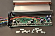
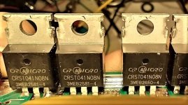
You can test for failed FETs using the info on the ebikes.ca Learn - Troubleshooting page, and buy new FETs to replace the failed ones (or all of the FETs if you prefer) with; typically it's a good idea to replace them with teh same part number as the FETs you're not replacing, so they all behave the same and share current as well as they can.
 
Oh this sounds exactly like what has happened.

So it looks like the blue phase is shorted and appears to be the negative fets. Oh boy, I have to un-solder all 3 fets? Each + and - fet has CRST041N08N on them. But below that is 3MEB2581-4 for the + ones and 3MEB2650-4 for the - ones.
 
Last edited:
Some controllers have what is called Slip Regen (there's other names for it as well, that I don't recall, most of them poor translations from Chinese). That behaves as you describe, where throttling somewhat rapidly down to zero lets you coast, but slowly down causes it to attempt to just follow the throttle-commanded speed.
I used that “feature” of the KT controllers when I was using brake lever regen but didn’t want the full/fixed/abrupt stopping power from the lever. With careful throttle control I could bring the bike down to about 7mph using the throttle before it would release/coast.
 
So it looks like the blue phase is shorted and appears to be the negative fets. Oh boy, I have to un-solder all 3 fets?
Just cut the legs at the body, then it's much easier to hold onto the bit of leftover leg on the PCB with needlenose/etc and unsolder/ remove each individual leg, since the FETs have failed you don't need to save them. There are threads here and webpages out there to show good ways to desolder FETs and solder new ones in, and how to do this for large-conductor PCB traces and what equipment you need to do that properly and easily without damaging the PCB or other components.


Each + and - fet has CRST041N08N on them. But below that is 3MEB2581-4 for the + ones and 3MEB2650-4 for the - ones.
I don't know what you mean by "below".

If you mean that the other phases use different FETs than the one that failed, it probably means the controller has already been repaired before, and the ones that are different are probably not original. (or they could be original and the others are replacements--the appearance of the solder joints should tell you which are factory).

If there are three FETs per phase for a 9FET controller, then it's not that unusual for the lower - half of the phase bridge to have different FETs than the upper + half, so those two phases are more likely to be original. In that event I recommend matching those for your replacements rather than the failed ones. (theres a thread from the last year or so discussing why the 9FET and 15FET controllers are even made, vs even-numbered-FET controllers).

I would guess that if you look up the specs for the different FETs you'll find that the failed ones have one or more specs that are not as good as the others. But it is also possible that the gate drivers on the failed ones were damaged by the original failure; if this is the case then that phase will always run differently than the other two. I haven't read the spec sheet but this is what a few seconds of google search turns up for the failed ones. Nothing turned up for the others, but I didn't check any variants of the numbers.

It is also possible that the failure happened not because the FETs were different or lower spec than the others or gate driver damage, but because of their soldering or mounting to the heatsink bar being inadequate or the insulation between back of FET and heatsink bar having a problem, so make sure that when you replace them that you make all these better than they were, and don't remove the heatsink bar, just remove the FETs you are replacing from it, leaving the others alone. (otherwise you have to ensure that those others are also adequately mounted to it and insulated from it.
 

Attachments

  • P020200618590843842120.pdf
    584.9 KB · Views: 4
Last edited:

Attachments

  • IMG_20230425_160216379_HDR.jpg
    IMG_20230425_160216379_HDR.jpg
    190.5 KB · Views: 9
  • IMG_20230425_161010928_HDR.jpg
    IMG_20230425_161010928_HDR.jpg
    105.1 KB · Views: 8
Last edited:
Oh sorry. Below the part number is more numbers, and the positives are different than the negatives. May not mean anything, not sure.
I think I understand what you mean, but a picture of the part number faces of FETs would make that certain. The numbers on non-tiny-SMT electronic parts generally contain a manufacturer part number and a date/manufacturing code. If you mean that both numbers you reference are on each FET, then since the one comes up as a part number the other is probably the date/manufacturing code (and thus isnt' found in a google search). What specifically that code means will be explained in a part's spec sheet for most manufacturers (some of them keep that data separate and you have to ask them for it, or they don't make it publicly available at all).

Be substituted not sure. Don't see anywhere to buy them.
If they are not available from anywhere, including Mouser, Avnet, Farnell, Digikey, etc., then you'd either have to message those places (most have some form of "chat" or a sales email address) with the spec sheet for them and ask for the closest equivalent that is better or equal, or determine that on your own from that spec sheet. There are a lot of characteristics, so it can be hard to make a really close match. If you tell them your purpose (ebike motor controller) it may help them be sure you get compatible parts (or it may make no difference; depends on who you get and what equivalents are available).

FWIW, the part number you gave does come up in a google search for places that list other places that sell parts, like this one
though I don't know if any of the places they list have any in stock or if they sell to individuals like the places I listed above do.

Keep in mind that depending on what happened when the FETs failed, they could have caused other damage (gate drivers, etc), so if it doesn't work after replacing the FETs, then those are usually the next thing to test (at that point you might need an oscilloscope to see if things are working as intended because simple voltage and resistance measurements no longer tell the whole story, if the parts are "working" but incorrectly...totally dead parts will still measure differently via resistances or voltage outputs...).
 
Last edited:
You have a point. Well for $65 it may just be throwed back in a dusty corner so I cannot see it.
 
Back
Top