crossbreak
1 MW
there has to be someone around here who has a good 2-linker. Just PM people
Whiplash said:I think I'll just mock it up in cardboard with swing arm and all in 2D and actually put wheels on it and everything once I get it close to perfect. I can't afford to waste the metal if I make it wrong...and cardboard is cheap!
Whiplash said:I've been staring at the motor trying to get a mount figured out and I think I'm good but I'm torn about mounting both chains onone side or doing it like cross suggested. His looks better and would be easier to package but requires you to push the motor if pedaled without power...

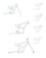
Whiplash said:Here's my first rendition of the main frame and swing arm in "CAD" lol!
I agree with 2moto.2moto said:That's not really the swinging arm position you're going to use, is it?
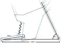
bandaro said:So here is what I have, way to close to it and pulling some blanks now, so opinions? Thinking brushed anodised aluminium tubes for the frame, and inside it a carbon box that holds the batts. latest image shows how the motor could get it's airflow via vents from the bottom, geometry follows a similar layout as other bikes, both high end DH, moto's and current electrics, so ergonomics should work nicely.
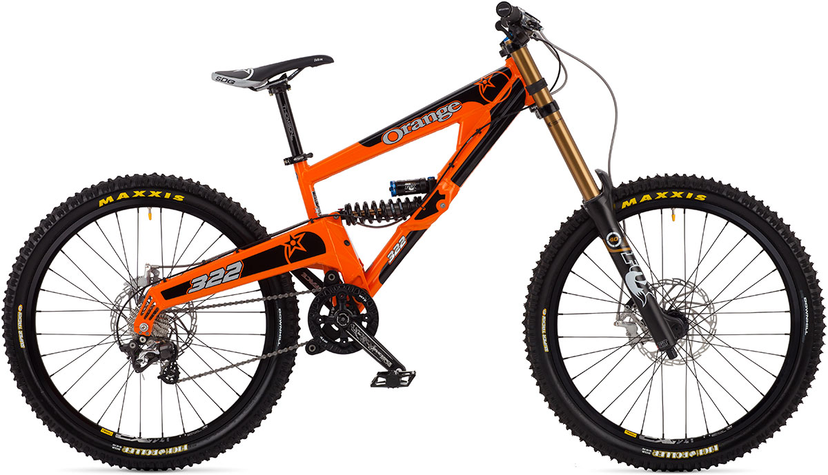
 The front suspension is woeful, though.
.jpg")
.jpg")
Whiplash said:After staring at it a bit, I think Im going to shorten the main frame at the back by an inch or two and open up the angle on the swin arm to get the rear tire farther away from the frame, it looks like it might hit in compression if I have any real travel and I am hoping to get at least 6-8" for a nice trail/moderate downhill ride...
???? you could loose 10% effciency and add 88.8wh (which would weight 0.124kg) and would still get equal and reach the top earlier btw...doing a lower weight build
2moto said:That looks pretty good. There are really two critical issues you have to get as best you can when designing two-wheeled suspension vehicles. One is chain tension variations. While a rear deraileur will accomodate chain length variations it will feel strange pedalling. If a motor drives it you will feel torque variations at the wheel due to chain tensions. Either way, it won't be nice and you WILL feel it when riding. The ideal solution to this is to locate the sprocket of the final drive chain concentric with the swinging arm pivot. If that is physically not possible, make it as close as possible. Given you'll probably need two chains, one connecting the BB to the motor, and the second to connect whichever one to the rear wheel, this should easily be possible.
The other what's called motion ratio. This it the ratio of the motion at the rear axle and the travel in the shock absorber. I would try for a ratio of no more than 4:1. This will give you a much nicer damping on the shock and allow to run a lighter spring. This is the major reason that cheap suspension bikes don't work very well and have to run massive spring rates. Good suspension design gets actually quite a bit more complicated as you need to consider progressiveness. That is, how does the spring rate vary over the total travel?
crossbreak said:with 44.4V/20ah you get 888Wh
If you really want to gain a benefit of the increased efficiency of your bike over a a single speed high power build, you have to add ENERGY to your battery. Otherwise a competitor could be as lightweight and hillclimbing as you are, doing a lower weight build