Switching from serial to parallel - kills controller?

BiGH

100 kW
Joined
Mar 28, 2007
Messages
1,085
Location
CBD - Melbourne
Hey everyone,
I've been posting sproadically, but came up with a design question for my bike.

I'm intending on running a BMC puma motor on the rear wheel with two of the EV-tech 37v battery packs. I've designed a 3 switch setup that can allow the running of either each pack individually, in series, or in parallel. Will this kill the controller? the batteries? or the motor?

My theory is to use 37v all day every day, unless i need a large speed boost, and then to use the ~74v mode

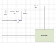
If u look at the picture below it could be setup that indicate something like this:
X Y Z Mode
0 0 0 Off
0 0 1 Batt 2 only
0 1 0 Series
0 1 1 ERROR
1 0 0 Batt 1 only
1 0 1 Parallel
1 1 0 ERROR
1 1 1 ERROR

now this could be setup with some simple logic to a 6 position rotary switch controlling relays.

Has anyone tried anything like this?
Is this bad for any component?
Is it not possible for some reason (I am a newbie in electrical engineering (but not digital logic) )

Got any general observations?

If this 2 way battery setup is possible, then i'm hoping it may be possible with a microprocessor to control 4, 8 or even 16 way setups.

Kindest Regards,
Haydon
 

Attachments

  • S-P Setup.png
    S-P Setup.png
    4.7 KB · Views: 2,558
now this could be setup with some simple logic to a 6 position rotary switch controlling relays.

Relays may not switch precisely simultaneously, leading to a catastrophic short -- potentially.

I ran into this problem while designing my 48V30ah <-->72V20AH switching system, and had to replace the relays with a 4-pole switch. A 3-pole switch though wouldn't work with your scheme though....

72_volt_48_volt_4pdt_circuit_156.gif


hmmm....I don't know how to make your circuit work in practice since a multi-pole switch doesn't have the flexibility to include and exclude all the logic possibilities, relays may not operate simultaneously, and neither would 3 discreet switches like your schematic shows.

Other than that minor problem, the logic looks OK to me!
 
i fail to see any purpose to this.
just put a pot in series w/throttle. Use switch for 74v(bypass pot).
 
xyster said:
hmmm....I don't know how to make your circuit work in practice since a multi-pole switch doesn't have the flexibility to include and exclude all the logic possibilities, relays may not operate simultaneously, and neither would 3 discreet switches like your schematic shows.

Other than that minor problem, the logic looks OK to me!

Sorry i didn't include this - I was going to make some digital logic to actually take care of that - basing a single input to select different relays to open.

I'll design up what i mean in a minute.

With the relay problem - thats somehting i thought of too. The stiuations that this would occur would be limited to only the opening of gates in the manner above that would cause an "error" or remaining in that state for a microsecond. ONe of the ideas i'm thinking of to overcome this is to have a "saftey switch" - that is activated much like when the clutch is used to change gears. the saftey switch isolates dificult parts until the relays have all switched over.
 
Matt Gruber said:
i fail to see any purpose to this.
just put a pot in series w/throttle. Use switch for 74v(bypass pot).
it's the job of the controller & throttle
What if u need 41v or 46v?
 
ONe of the ideas i'm thinking of to overcome this is to have a "saftey switch" - that is activated much like when the clutch is used to change gears. the saftey switch isolates dificult parts until the relays have all switched over.

How would you implement this safety switch (is it a timing circuit)?
What if a relay fails to switch at all?
 
When switching battery voltages, there will be a large current spike caused by the main capacitors in the controller. This can sometimes lead to contact sticking or failure. If the switch is large enough, it should handle it.

I don't think there's many times you would want to run on half a battery pack. Performance will almost always be better if you run both in parallel due to less resistance losses. If one failed, then I could maybe see it.

There is only a slight advantage to running at half voltage for lower speeds. You could permanently keep the batteries in series and just use the throttle to limit the voltage.
 
I also appreciate what Matt and Fechter are saying, but there seems to me a couple practical reasons for a pack-switching scheme like this:

1)so you can ride one pack out, and then the other pack back, minus the worry of where exactly the half-drained point is, then engaging both packs in series when you need extra go also drains both equally.
2)better throttle control if riding a lot at slow speeds.

So a system like this seems to me a method for practical battery monitoring, and speed fine-tuning, and not a performance enhancement of any sort.
 
Matt Gruber said:
i fail to see any purpose to this.
just put a pot in series w/throttle. Use switch for 74v(bypass pot).

Hi matt,
The idea is to change the pack voltage to provide less power to the controller. From Knoxie's 80v test video, you can see that there is a lot more force initially when he's using 2x batteries in series from rest. My idea is to limit this initial kick at startoff, and then once the bike is moving and only use the 74v mode for high speed riding.

Its highly likely (possible) i'm wrong on this though. with the setup you describe would it be possible to be able to control the motor to turn at very low speed? or would it become more like a binary switch?

I like your idea :D


Kindest Regards,
Haydon
 
fechter said:
I don't think there's many times you would want to run on half a battery pack. Performance will almost always be better if you run both in parallel due to less resistance losses. If one failed, then I could maybe see it.

Very interesting - you have a good point there. I tend to agree. My idea was that under normal conditions the pack would be run in "parallel" or normal mode.

high speed would necessitate "series" connections

the individual cells would basically only be used if:
a) there was a fault in one of the cells
b) i left one of the cells at home do maximise carying space

if it was reliable enough then it could open the door for smoother low speed acceleration and less force being applied to the frame of the bike (my main goal)
 
xyster said:
ONe of the ideas i'm thinking of to overcome this is to have a "saftey switch" - that is activated much like when the clutch is used to change gears. the saftey switch isolates dificult parts until the relays have all switched over.

How would you implement this safety switch (is it a timing circuit)?
What if a relay fails to switch at all?

Thats something i haven't explored yet! I was thinking of maybe just starting with a manual switch.
 
xyster said:
I also appreciate what Matt and Fechter are saying, but there seems to me a couple practical reasons for a pack-switching scheme like this:

1)so you can ride one pack out, and then the other pack back, minus the worry of where exactly the half-drained point is, then engaging both packs in series when you need extra go also drains both equally.
2)better throttle control if riding a lot at slow speeds.

So a system like this seems to me a method for practical battery monitoring, and speed fine-tuning, and not a performance enhancement of any sort.

#1 is faulty logic.
A. it often windy, or hilly in 1 direction.
B. all batteries last longer operating together(Peukert)

#2. a crummy throttle should be fixed(add pot).

#3.(BTW) add pots to your chargers to adjust charge level (pot is addictive)
 
#1 is faulty logic.
A. it often windy, or hilly in 1 direction.
B. all batteries last longer operating together(Peukert)

A. Often not enough to make a significant difference in ride distance. Besides, one battery being lower than the other is better than running out of juice totally -- you can always switch back to the battery with remaining charge.

B. Peukert effect is minimal for all but SLA batteries.
#2. a crummy throttle should be fixed(add pot).
Agreed this is the simpler, more effective hack for speed fine-tuning.

#3.(BTW) add pots to your chargers to adjust charge level (pot is addictive)
Between your motorized beach-chair project and apparent inability to shop for groceries while walking upright like the rest of us able-bodied bipedal monkeys, Gruber, you're a perfect example of pot leading to brain cells frying. :D
JK...

...mostly...:D
 
Pukert severe w/lithium.
15ah pack
10ah=high drain
12ah=med.
foolish to waste even 2ah
 
Matt Gruber said:
Pukert severe w/lithium.
15ah pack
10ah=high drain
12ah=med.
foolish to waste even 2ah

From where did you get that? The discussion of the different LVC's of the EV Tech packs?
Me think you are confusing increased voltage sag under high loads with the peukert effect.

Folks who have posted measurements of their NiMH and lithiums here, like Lowell's 18ah-rated NiMH (really 19.5ah) and Mahoney's lithium 18650s are getting close to, or more than, 100% the rated capacity.

At 1C, lead acid batteries are only good for one-half their rated capacity.

http://www.batteryuniversity.com/partone-16a.htm
 

Attachments

  • puke-ert.jpg
    puke-ert.jpg
    23 KB · Views: 2,480
Yes.
my impression is the 15ah pack
only delivers 10ah at high drain.
whatever the cause, it sucks, and is not smart to run 1 pack at a time.
 
Back
Top