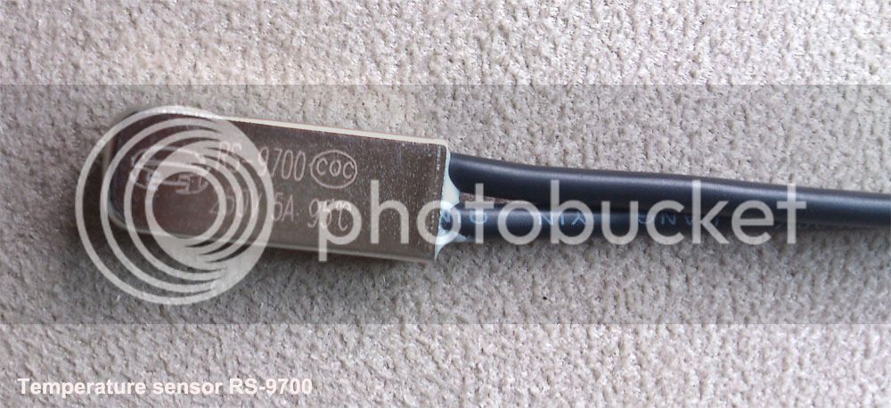
Temp sensor that's too cool not to share

From John in CR: http://endless-sphere.com/forums/viewtopic.php?f=2&t=44529#p648292
Move the thermistor switch to the stator steel near the windings instead of attached directly to the windings. That's where the motor factory installs the thermistor on the high efficiency hubbies I use. They use a 95°C trigger temp, but these motors have a lot more steel and the thermistor is at least 1cm from the windings. That way the short spikes in winding temps don't trigger the switch and it's better tied to the stator temp as a whole.

From passpato: http://endless-sphere.com/forums/viewtopic.php?f=3&t=39790
I have discovered that the max temp for the [Heinzmann] motor is 125 degrees C

_70C = 160F
_93C = 200F
125C = 257F

The LM35 sensors I've looked at range from freezing up to 150C / 302F

http://endless-sphere.com/forums/viewtopic.php?f=3&t=53040&p=788864#p790209
My crystalyte fried when I was cruising around the neighborhood, I wasn't pushing it hard or racing or anything. My motor started intermittently jittering every 10 minutes or so (for a second or two). The temp gauge started to rapidly rise from 80 celcius to 110c. Once the motor hit 115C the motor stopped working and all throttle inputs solely resulted in only motor jittering. The motor smelled of smoke (I had a drilled side cover).
When I got home I opened the motor cover and found that a bearing had ground down the phase wires and shorted two of them together. I soldered on new phase wires added a piece of plastic as a barrier to the wires, put everything back together again and everything was working great for about 30 seconds then went back into jitter mode and smelled of smoke again. I tore the motor down again and found a black char mark on one of the copper wires (windings I think they are called?).

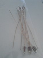
From Kepler, drilling a small-diameter hole in the axle and inserting two-wire 10K thermistor to check against internal temps to see if the reaction time was adequate to make this a viable option for temp sensing without dis-assembly of the motor, or running wires through the hollow axle side (which is squeezed due to fat phase wires)

http://endless-sphere.com/forums/viewtopic.php?f=4&t=37964&start=1450#p733858
http://endless-sphere.com/forums/viewtopic.php?f=2&t=53436
Needed a starting point to set the CA to so I went with temperatures I typically see on the motor casing when measuring with a infrared thermometer. I know from previous experience including motor failures that 55 degC (on the sideplate) is a safe max temperature with anything over 60 degC being dangerous territory. with this in mind, rollback was set to 50 degC and cutout to 60 degC as a starting point.

So off for a ride at one of my local torture tracks to get some data.

First thing I noticed was that the temp at the motor shaft was surprisingly reactive to changes in motor load. Hard hill climbs would see temps rise quickly with coasting down the other side quickly seeing temps drop off again. My expectations were that the heat sink effect of the stator and motor shaft would make temperature reactions very slow but this certainly wasn't the case.

Every few minutes I would stop and measure the motor casing with my infrared thermometer and discovered that the two temperatures tracked quite closely but with a DeltT of around 8K (shaft temperature showing approx 8 degC lower then the motor case).

So with the data collected, l set the CA up for 42 degC rollback and 52 degC cutout (at the center of the axle).
 
I used this. http://www.canakit.com/4-digit-led-thermometer-kit-ck127-uk127.html
I took some ribbon wire and run the sensor to a set of fets and it works very well.
 
For anyone who wants to use a CycleAnalyst, you might want to use a compatible sensor so you can access all of the CA functions, rather than just readout the temps. From ebikes.ca:

All of these Crystalyte hub motors now have a built in 10K NTC thermistor, enabling you to monitor motor temperature with the CA3 providing a safety roll back. This allows you to get the most short-term power from the hub without risk of overheating from prolonged use.
 
I am surprised it took so long for me to get a temp probe. I placed two orders, and the order on Ebay from China got here first.

If somebody wants one, I will mail you one (plus 3 sections of 2mm heat-shrink) if you paypal me $2, for anyone in North America (postage is included), PM me for my paypal address. It's an LM35 purchased from ebay vendor "gc_supermarket", labeled "10PCS LM35DZ TO-92 IC SENSOR PRECISION TEMP NEW GOOD QUALITY"

http://www.ebay.com/itm/290937261807?ssPageName=STRK:MEWNX:IT&_trksid=p3984.m1497.l2649

cross-link to the sale thread:
http://endless-sphere.com/forums/viewtopic.php?f=31&t=52014

006.JPG
 
These were a pain to solder with my poor vision and fat gorilla-fingers. I recommend getting those geeky glasses that have a light built into them and highly magnifying lenses. 2mm heat-shrink from Hobby-King seems to be adequate. 2mm was the smallest they have right now, I would prefer 1.5mm, so I will keep looking for that.

Temp sensor2 003.JPG


RCcolorCode.png
 
When really pressed for small insulation sleeves, you can also strip it off existing wires you don't need anymore, and slide it over the leads. With some types of insulation they're stretchy enough to go over the soldered joint, if it's not too big or blobby. Mostly this works best with a lap joint of some type, which I think is why I originally started joining wires by "fraying" the ends and then pushing htem into each other, then "rolling" the resulting joint so it ends up no thicker than the actual insulation of the wires, in total, including hte solder done after this.
 
Good idea! I stripped some insulation off of junk wire I scavenge from electronics/vacuums/etc sitting on top of bins on collection-day. I stripped them to get some strands for wrapping a joint before soldering. I can now imagine sliding a section of stripped insulation over a soldered joint, and then sliding some heat shrink over that, to make the insulation over the joint very snug.

The 2mm heat shrink was reasonably snug on the fat soldered section (only fat because of me being in a hurry and sloppy), but the ends didn't shrink down enough to be snug on the original wire.

On a hunch (since the LM35 is used for the LiPo charger "hot battery" cutoff) I searched Hobby-King for "LM35", and they do indeed sell them. They come mounted on a small circuit board with a male 3-wire connector on the end, which looks like a standard ESC wire plug. It's $4 (instead of $1 each when you buy ten from an electronics supplier) , but if you're wanting only one and you are placing an order anyways, adding this light component to the package wouldn't hurt the shipping cost. Note: every order from Hobby-King, I add some heat shrink, it's dirt cheap and light.

Question: does anybody know if "JB-Weld" or "DP-420" is electrically conductive? By that I mean when I epoxy the sensor to the stator, can I also add extra to cover the leads from the sensor to the RC-connector? several posters have responded that JB-Weld/DP-420 and other common epoxies are NOT conductive. This means that they can be used to attach the sensor to some internal motor/controller part, but also they can cover that part and the wire connection as a water-proof insulator.

http://www.hobbyking.com/hobbyking/store/__26898__Arduino_LM35_Linear_Temperature_Sensor_Module.html
26898(1).jpg
 
spinningmagnets said:
Question: does anybody know if "JB-Weld" or "DP-420" is electrically conductive? By that I mean when I epoxy the sensor to the stator, can I also add extra to cover the leads from the sensor to the RC-connector?
I don't know for sure, but JB-Weld claims to have metal particles mixed into it, so I would not count on it being non-conductive, just in case the JB-Weld marketing department were accidentally telling the truth.
 
How high of a temperature will the LM35 sensor take?

I need to build a temp sensor for my eBike and my Motorcycle.

I have a couple of temp sensors I bought off eBay in the mail. The sensor from Hobby King looks like what I really need.
http://www.hobbyking.com/hobbyking/store/__9744__Hobby_King_Voltage_Temperature_Monitor_2_6S_0_150C_.html?gclid=CN3imZDrlLkCFWNxQgodwUcAKg

Hobby King sensor explained.
http://www.youtube.com/watch?v=srdGCUvstaA
 
How high of a temperature will the LM35 sensor take?

The LM35 sensors I've looked at range from freezing up to 150C / 302F,

...95C / 203F is a common limit that the motor or controller should not exceed.

...70C / 160F would be a reasonable temp to start limiting amps to avoid higher temps.

xxxxxxxxxxxxxxxxxxxxxxxxxxxxxxxxxxxxxxxxxxxxxxxxxxxxxxxxxxxxx

1/16th inch diameter 2:1 heat shrink http://www.bphobbies.com/view.asp?id=A0320123&pid=T537985
2:1 shrink ratio and 3:1 shrink available in 1/16", 3/32", and 1/8" on ebay.

xxxxxxxxxxxxxxxxxxxxxxxxxxxxxxxxxxxxxxxxxxxxxxxxxxxxxxxxxxxxxx

My order of "micro-servo" socket pigtails arrived. I have found that it is much easier to solder butt-splices to a couple of wire ends and slide heat shrink over the joint, compared to soldering wires onto the three legs of the LM35 temp sensor. The larger socket on the right in the pic is the standard size servo socket.

The three legs are flat blades. But, they are facing the wrong way, so I not only trimmed them shorter, I also twisted them 90-degrees with needle-nose pliers so they would insert into the micro-sockets.

The "micro" size uses very thin 32-Ga wire, $1.20 for five, took two weeks to arrive with cheapest shipping.
If the link below doesn't work in the future, I found them at Hobby King in: hardware & accessories/wires & plugs

http://www.hobbyking.com/hobbyking/...or_Lead_1_25_Pitch_Female_Plug_5pcs_bag_.html

tempSensor 004.JPG

tempSensor 001.JPG

tempSensor 005.JPG

If you like these smaller connectors as a female socket for the 3-leg LM35, I believe you can also use an "ST XH 2S 7.4v Lipo Balance Wire Extension Lead 8.5in"
 
There is a big difference in the LM35 and the LM335 sensors. The LM35 (shown in posts above) can provide a signal where each degree of temp in centigrade is equal to 1/10 of a volt, so...0.40V = 40-degrees Celcius. In this way, a simple and cheap digital voltmeter can be used as a thermometer.

The popular CycleAnalyst has some very useful features. The latest version can monitor the temps of the battery/controller/motor, and if any are reaching an adjustable warning set-point, the CA can temporarily "roll back" the max amps allowable until the part in question cools down some and the danger is past. However, the LM 35 is not calibrated to allow it to perform that function.

The physically similar LM335 is the sensor that will accomplish this valuable and useful task (also <$1 each to buy in bulk). I have ordered ten of them, and if it goes well, I will post the link for others, and I will make them available, packaged with appropriate heat-shrink.

Here's the PM from Justin LE:

LM335 is super easy to use since it behaves like a zener diode and can make use of the onboard pull-up resistor in the CA. You need to get the polarity right (- of the sensor goes to the gnd pin on the CA plug, + of sensor goes to the signal input of CA plug). Use the linear sensor option, set your 0 degrees voltage at 2.73 (273kelvin), and the scaling to 100 degrees / Volt (same as 10mV/deg), and it should be good to go.

Any temperature sensor with a linear or approximately linear output can work in linear mode, and a 10K NTC thermistor with a 3900-4000 beta constant will work fine for the thermistor mode.

In a scramble mode getting stuff ready for exhibit at the Xtracycle booth in the outdoors demo at InterBike in Las Vegas.

http://www.basicmicro.com/Temperature-Sensor-LM335_p_209.html
 
JB Weld is not electrically conductive. I looked into this at some point while determining thermal conductivity. I added aluminum filings to some to increase thermal conductivity, and wondered about the effects. There is even a video somebody put out regarding electrical conductivity with various levels of filing addition:
[youtube]9gKYfgIGMlE[/youtube]
Looked convincing to me.
 
Thought id post these,
I like them because they are tiny, rated for upto 300c
Its just a 100k thermistor
Tolerance -5% to +5%
Bead Dia 1.83mm length 3.66mm
They can be purchased individually for about $1.50
https://www.bilbycnc.com.au/DispCat.asp?CatID=9&SubCatID=101

I have run them at 260c for over 24 hours, very consistent readings, i have not broken one of these yet. Some in the past have been very brittle at the base of the bead where the wires go in, can imagine if you epoxy them in, that would be less of a concern.

they have really good wires and dont break to easy, can be easily soldered or spot welded onto your wiring.
I am thinking i might make a simple arduino setup with an lcd, and if you wanted to make it more complex, you could connect it to your phone, more programming effort tho.
I saw some cheap lcd's that will actually do a graph, about 2x2 inch so you can see the previous temp readings,
im getting right into arduino atm.
 

Attachments

  • IMG_20130912_132503.jpg
    IMG_20130912_132503.jpg
    97.9 KB · Views: 5,373
spinningmagnets said:
"The Crown" hubmotor from Crystalyte uses an RS-9700 temp sensor that is pre-installed at the factory..

http://endless-sphere.com/forums/viewtopic.php?f=3&t=50860#p752946
http://i189.photobucket.com/albums/z313/sacko_vit/temperaturesensorrs97001_zps1824eca6.jpg
Technically I don't think that's a "temperature sensor" but rather just a thermal switch, that operates (breaks connection) at 95C, if it's like the others I've seen like that.
 
Who is running a voltage read-out on a MAC with the factory LM35 temp sensor?

What digital voltage read-out are you using?

Would I need to tap into the 5V throttle power-supply wire to power the LM35?
 
If you have a Cycle Analyst, there is no benefit to the LM35, the 10K thermistor is the desirable sensor for the CA. Many geared hub MACs are being bought with the factory LM35 installed. I was just wondering what ways are being used to get the factory LM35 to read out...
 
Back
Top