My "Mark 2" solar trailer

EwanC

1 mW
Joined
Jan 17, 2021
Messages
18
Hi E-S,

I'm about to start on a "Mark 2" solar trailer project and thought I'd post a build thread on here, for advice from the experts and hopefully to make some contributions to the pool of knowledge on the topic. It'll be inspired by @solarEbike's impressive contraption - he's well and truly proven how feasible this solar trailer thing is.

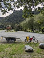
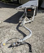
But first, I thought I'd talk about my "Mark 1" trailer. I put together this contraption a couple of years ago and I've got maybe 2500km on it now. The structural parts are aluminium, built for me by Steve from cycletrailers.co.nz. I designed it to support two Sunman eArc 185W flexible solar panels, each of which measures 1520*680mm. Total length is 4200mm including the drawbar. Width, at the widest point, is 750mm. It has aluminium support ribs under every cell. The panels are secured to the aluminium support ribs with VHB foam core tape (GPH-160GF, 12*1.6mm) - the idea being to allow for some thermal expansion/contraction. It uses an Elejoy boost MPPT solar charge controller from ebikes.ca, with the panels in series. It has 20" wheels with 14mm BMX axles, and Schwalbe Super Moto-X 20x2.4 tyres. It attaches to my bike with a standard Burley trailer hitch, and has a Burley flex connector in the drawbar of the trailer. The panels can rotate maybe ±30° (manually, using seatpost quick-releases at either end to secure it). I tow the trailer with a fairly typical converted hardtail bike. The bike has a GMAC motor in the rear, driven by a Frankenrunner controller, with a 14S7P (52V) EM3EV rectangle battery containing LG HG2 cells. It has space under the panels for two 100L plastic crates that sit on aluminium angle runners (see the pics).

PXL_20221231_012149241.jpg
Mark 1 works pretty well. It has heaps of power - I don't doubt the panels are performing to spec (though I don't have an irradiance meter to prove it). On a sunny day, it'll give me 350W+ for an extended time, and I've seen it peak up to 450W. It handles shingle/dirt roads without any trouble even though it has no suspension. It has far more storage space than I need. But it has some drawbacks that I want to address with a Mark 2. In particular, it's quite heavy - around 28kg without the crates (edit: I finally weighed it and it's 34kg without crates, and the empty crates make it 40kg). It needed quite a lot of aluminium for sufficient stiffness down the length. The length doesn't bother me much when underway (just need to be careful around tight corners in town), but the length makes it annoying to transport e.g. on a trailer behind a car. That it's welded together means it can't really be disassembled for transport. 370W of solar is overkill for my usage too tbh - I don't go fast enough to use so much power when the sun is out, so some of that power goes unused on nice days. Still, I've done some decent multi-day tours with it, including a fair bit off pavement (e.g. the Molesworth Station here in NZ).

My goals for a Mark 2 trailer are:
  • Significant weight reduction. Aiming for a 22kg weight loss, for a total trailer weight (excluding any gear) of 12kg. That's pretty ambitious, I know, but I'm going to try.
  • Able to be disassembled into pieces each of which are no more than 900*900*50mm. This means I can break it down and fit it in the boot of my car, or very easily on a typical light trailer behind a car. I won't be doing any round-the-world trips any time soon, but I like the idea of being able to drive to a different region, do a few days' loop tour, then come home again.
  • ~250W panel power. That should be plenty and it'll make the trailer much shorter/lighter. I don't want to go as low as 200W because my wife sometimes comes along on trips and we share the available energy (we swap batteries). We'll have a child trailer too, so only one of us can have solar!
  • A little storage space - I'm imagining a tray for a 50-100L PVC dry bag to be strapped on. I have 200L now and could probably fit 400L of crates, but I already tend to over-pack.
  • Somewhere I can put a linear actuator for single-axis sun tracking. I'd love a motor inside the main boom to track the sun like @solarEbike did, but the mechanical complexity is beyond me. I plan to design/build/program my own tracking computer (I studied embedded systems/electronics engineering many years ago, though I didn't end up doing that for a living). I'll leave this for later though - I'll have a manual tilt to begin with.

I'll use two LightLeaf Solar gLeaf panels. I've already ordered the panels. Rick and Eric have kindly agreed to make me some custom sized panels - 6x6 cells, to fit within my self-imposed size limit. I plan to use carbon fibre tubes to form the supporting structure, with an off-the-shelf tube connector system. I have some very basic fabrication skills and tools, plus I have a drill press and the skill to operate it, but I don't have any experience working with composites. The budget is 7500NZD (much of that will be eaten up by freight costs here to the bottom of the world!). Will write more about my ideas for the Mark 2 trailer in the next post. In the meantime, any thoughts are most welcome :)
 

Attachments

  • PXL_20220223_223755722.jpg
    PXL_20220223_223755722.jpg
    4.1 MB · Views: 40
  • PXL_20230401_234027069.jpg
    PXL_20230401_234027069.jpg
    3.2 MB · Views: 42
  • PXL_20230401_233845758 (2).jpg
    PXL_20230401_233845758 (2).jpg
    4.5 MB · Views: 35
Last edited:
Very interesting and cool! Any thoughts to add some aerodynamic elements to reduce drag? That would seem to be almost as important as weight reduction.
 
Very interesting and cool! Any thoughts to add some aerodynamic elements to reduce drag? That would seem to be almost as important as weight reduction.
Thanks, lots of work yet to do though! Hmm I hadn't really thought about aerodynamics much tbh. Those crates are probably pretty terrible for aerodynamics, so I suppose there'll be some gain by getting rid of them. I figured that at my cruising speed of 20-25km/h then aerodynamics just aren't that important compared to weight. That seemed to be @solarEbike's conclusion after he did a bunch of testing e.g. here Around the world on a solar ebike.
 
Solar panels
As mentioned above, I've already ordered two LightLeaf Solar gLeaf panels, in the 6x6 cell arrangement (about 830*830mm each). I considered flexible EFTE panels (e.g. Solbian), but the necessary support structure adds a lot to the weight and cost. Those LightLeaf panels seem pretty compelling for this application. I don't have specs for the panels, but extrapolating from the 4x8 model, I think they'll have a Voc of 26.4V, Vmpp of 22.5V, and Impp of 5.54A, for a nominal power output of 124W each. I'll be charging a 14S battery, so I'll need to have the panels in parallel - if they were in series, the Voc would end up as 52.8V, which means I'd have to be above ~60% SoC to be able to charge with a boost-type controller. Nobody makes a buck-boost solar controller as far as I know :(

Fork
I'm going to buy an off-the-shelf fork/yoke to connect the trailer. I've found 3 options so far:
  • Burley Coho XC yoke. No weight info available online, but I contacted Burley and was told this part has a shipping weight of 1.87kg. Quite a lot. Not cheap either.
  • Extrawheel fork. Lighter, at 1.2kg, but the attachment mechanism between the trailer and fork seems very specific to the Extrawheel and I'm worried it'd be at risk of popping off on rough tracks.
  • BOB fork. Not entirely clear how heavy it is, but the best info I have is that it's 1.3kg. Looks easy to make a compatible trailer too (a pair of M6 holes a certain distance apart will allow the trailer and yoke to fasten together). That's the winner I think. (edit: I weighed it once it arrived, it's 1.28kg).

Carbon fibre connector system
I'll have to use carbon fibre to reach the weight goal, but I don't have the skills to fabricate my own carbon fibre joints. Ease of disassembly is also a goal. So I plan to use an off-the-shelf connector system. The two I've considered are:
  • Rock West Composites' Carbonnect system. They do it in 1.0", 1.5", or 2.0", so the size options are ideal. Unfortunately they won't export it to me as a dodgy foreigner. So that leaves:
  • This tube connector system from dragonplate.com. There's a whole range of connectors available - just need to cut tubes to length, roughen them up inside, and epoxy the connectors into the tube. Then they bolt together. Unfortunately the largest size they offer is 1.0", which is a bit on the small side IMO. So I'll have a truss arrangement - a top boom, a bottom boom, and 45° braces between them in order to stiffen up the structure. The weight does add up - the design I have in mind would result in ~1.25kg of connectors and ~1.1kg of CF tubes.

Solar controller
I've considered two different controllers:
  • Genasun GVB-8-WP-Li-58.4. 0.29kg each, fully potted, high quality gear. Unfortunately, with the max Impp rating of 9A I'd need two of them, so that's 0.58kg. They're also maybe 370NZD each delivered, quite a big chunk of the budget.
  • This "Elejoy" model from ebikes.ca. 0.46kg, so a little lighter, but much cheaper, probably 200NZD delivered. I've got this on the Mark 1 trailer and it works well. It's only "water resistant" though (I added some sealant to mine and used it in heavy rain without problems, YMMV). It's also maybe 2-3% less efficient than the Genasun (discussed elsewhere on E-S).
Going to defer this decision until I know if I can spare the extra weight/cost for the Genasun units.

Fork
I've come across some fairly cheap carbon fibre forks on Ebay - this sort of thing. 0.4kg or so. Considering the cost, they seem too good to be true - has anyone used this sort of thing before? I'm sure the $1,000 name-brand carbon forks are great, but that'd take too much of the budget here. I figure maybe even if they're not the strongest ever, they'll be relatively lightly loaded compared to a normal bike fork so hopefully I'll get away with it.
 
Last edited:
Step up mppt


SUNYIMA 300W MPPT Solar Laderegler Boost 24V 48V 72V​

12-50V input 24-72V Output

never had one of them, they offer 300W and 600W
 
Really interesting project good luck.

By the way you can get a ' buck-boost solar controller' and cheap too, I have one which I had intended using for a similar project.


(I didn't get mine from here just giving an example)

You can set the exact output voltage digitally.

I don't have a link, but someone did a test against the genasun unit and there's only a few % difference in efficiency but the genasun MPPT algorithm is a bit quicker to operate, but it's nearly 10x the price.

EDIT: Ah I see domink h beat me too it....
 
Thanks @dominik h and @kudos . I hadn't really considered that CTK-EV-300 model tbh, I knew it existed because Grin used to sell that model but they've discontinued it. Are you certain it's a buck-boost topology? Afaik, even the very costly Genasun units are boost-only (i.e. they won't start if Vin > Vout). Looks like @solarEbike has done some efficiency measurements of the CTK-EV-300 but I can't find his results.

Fwiw, I found an efficiency comparison between the MPT-7210A and the Genasun GVB-8 on here, showing 87.3% efficiency for the MPT-7210A and 94.5% for the GVB-8, but it was at relatively low power levels so can't really be taken as a general result. There's a also a bunch of graphs on that thread for the GVB-8's efficiency at a range of operating points (but no equivalents for the MPT-7210A). I'd discounted the MPT-7210A early due to the fan (that'd surely get gummed up with dust in a heartbeat) and lots of E-S members reporting poor MPPT tracking with it too.
 
You can mod the fan on the mpt7210 if you're worried about dust. And it certainly does have poor tracking, but in my opinon, the efficiency losses are offset by the price and its adjustable voltage range
 
I spent some time looking more at the MPT-7210A and CTK-EV-300. Interestingly, with the MPT-7210A, if you have a panel Vin > battery Vout, it doesn't error out - it basically shorts the panel to the battery while panel voltage > battery voltage, so the resulting charge current can be read off the panel's IV curve. I don't know if the configured max Vout (i.e. the CV phase voltage specified) would be respected in this case though.

Now, this begs the question - does the Elejoy boost solar charge controller have the same behaviour? I took out the Mark 1 trailer today and did an experiment. With no battery connected to the Elejoy, it reported a Voc of ~48.1V (as expected, my panels on the Mark 1 are in series). I discharged my 14S battery down to ~44V with a controlled load test device. So when I connect the battery to the Elejoy, Vin > Vout. It worked fine though - Vin immediately fell below Vout (as expected, since Vmpp for these panels is below the battery voltage at the time), no protections triggered, no smoke came out. Max output voltage on the Elejoy was set to 56.4V, so the experiment doesn't show whether or not the max output voltage is still respected if Vin > Vout.

I think I'll go with the Elejoy - it's so cheap, has adjustable voltage range, somewhat water/dustproof (listings on Aliexpress say it's IP66 but I find that hard to believe!), and no moving parts.
 
Thought I'd better offer a progress report on this project. I've spent a lot of time learning enough Fusion360 to design the trailer in CAD, so that I could calculate the carbon fibre tube lengths and avoid any expensive screw-ups. I'll need to use quite a few DragonPlate CF tube connectors, which have various lengths/thread/hole offsets from the tubes they'll be attached to, and it was proving to be quite difficult to design with confidence on paper. The connectors are permanently glued into the tubes, so if I make a mistake then I'll need to get new connectors and tubes. Designing the rotation mechanism was also too hard on paper. So I gave up on paper and spent a lot of time with Fusion360. Here's the result so far:

Trailer_v2_2023-Aug-03_09-08-16AM-000_CustomizedView2643895011.png

You can see it uses various aluminium connectors at the end of each tube, and CF mounting brackets to create more complicated joints. This means it can be disassembled into a bunch of tubes that can then easily fit in my car boot.
The linear actuator is a Firgelli FA-B-110-24V-4. I've modelled the rotation in Fusion360 so as to find a good mounting position and choose an actuator stroke length. The position allows a panel rotation roughly ±65°, which should be plenty. The actuator is capable of ~500N force (50kg/110lb), which is an awful lot. I think there'd need to be ~15-20m/s difference in wind speed between the top half and bottom half of the panel before the actuator would be unable to hold. The downside to a high-force actuator is that it'll take almost 20 seconds to rotate all the way from one side to the other, but I figure it'll only need to do large rotations when I do U-turns, and that's rare.
The shock in the model isn't the same one I'll use - I just grabbed a CAD model online of a different shock with the same mounting geometry and stroke length.
The BOB yoke arms aren't shown - just the cylinder piece of the BOB yoke that the trailer will mount to via a piece of M6 threaded rod.
The brackets that mount the panels to the top tube will have a hole slightly bigger than the tube diameter, and I'll apply UHMW tape to the inside of the hole, to allow for rotation. Hopefully that's good enough - I know CF isn't great under abrasion so I'll need to keep a close eye on the top tube for any damage where the panels rotate about the tube. This solution is simple and light though.

Pretty much all parts have been ordered, and a bunch of stuff has arrived already:
PXL_20230803_090416446.jpg

The weight budget has blown out a little unfortunately - my spreadsheet says it's up to 14.85kg now, including the BOB yoke and weight of an empty Ortlieb Rack-Pack 49L on the cargo tray, but not including various fasteners and cables. So it'll probably end up a tad over 15kg. On the upside, I finally weighed my "Mark 1" trailer, and it turned out to be 12kg heavier than I thought (it's just over 40kg with empty crates but I thought 28kg). So the "Mark 2" trailer will have a 25kg weight advantage even though I've blown the weight budget a little.

The cost budget has also blown out a little - 8200NZD spent so far, out of an original budget of 7500NZD. Almost nothing left to buy though.
 
Interesting design - I am just sort of eyeballing from the armchair here, but overall it seems to have a lot, or even excessive amount of 'vertical' rigidity. But I see essentially nothing to stop 'torsional' flex/bending. If the joints were very well filleted carbon fiber tube-to-tube joints, that would help. But it seems like the tubes go to an aluminum connector which is bolted to a thin aluminum plate on the adjoining tube? Seems like that would twist quite a lot.

Then this is all balanced on one wheel? So you are expecting the trailer hitch / draw bar to restrain all twisting motion? Even a few degrees of twist at a hitch would be several inches of swaying at the top of the solar panel. Guess this could be absolutely rigid to the bike, but then it seems you would be in somewhat of a bind because the bike needs to lean to go around corners - you and the panels could all lean as one unit, but that seems like a LOT of 'sail area' to control even in very light breezes?

So overall, the main thing I see is that the 'Mark 1' - the stability was provided by the trailer itself and seems like the bike was free to turn independently. The 'Mark 2' - with one wheel - seems like the bike now needs to provide all stability which seems like it would put a huge load on the rider in anything but absolutely calm conditions?

Anyway, looking forward to seeing this come together! Super nice drawings and keep up the good work!
 
Interesting design - I am just sort of eyeballing from the armchair here, but overall it seems to have a lot, or even excessive amount of 'vertical' rigidity. But I see essentially nothing to stop 'torsional' flex/bending. If the joints were very well filleted carbon fiber tube-to-tube joints, that would help. But it seems like the tubes go to an aluminum connector which is bolted to a thin aluminum plate on the adjoining tube? Seems like that would twist quite a lot.
Thanks for your thoughts. I'm definitely concerned about torsional flexing down the length. It was pretty easy to add bracing to help with the 'vertical' rigidity. On the Mark 1 trailer, 'vertical' flex down the length was a problem so perhaps I've gone overboard with 'vertical' bracing on the Mark 2. It's easy enough to remove one or two of those braces if they turn out to be unnecessary though.
I found it much harder to stiffen "Mark 2" against torsional flex. I considered having a triangular profile when looking down the length of the trailer (i.e. one upper tube and two lower tubes running down the length, connected vertically/horizontally into a triangle), which would resist torsional flexing much better but it would add a lot of weight and cost. So I hoped that the upper tube + braces would have enough stiffness to resist the bending that'd need to happen for the trailer to flex down its length. Modelling or calculating that is beyond my mechanical design skills unfortunately. If the tabs where the braces attach to the upper/lower tubes end up flexing, I can reinforce those easily enough.

It wouldn't be so easy to reinforce that upper front joint later though. Is that the one you're concerned about? It consists of this connector on the front vertical tube (which has a threaded steel insert to tighten a screw against, CAD model doesn't show it for some reason):
FDPCK-MC1-S-ENDTHRD_drawing.png
And this connector on the horizontal tube (it's not threaded even though the CAD model shows it being threaded, I really should fix that):
FDPCK-MODCON1-SS-FMLE drawing.png
The connectors insert ~50mm into the respective tubes and will be bonded to the tube internally with 3M 2216 epoxy. They'll be fastened together with a 1/4-20 screw, which I plan to tighten up fairly firmly (I had something like 15Nm in mind). It definitely wouldn't be as good as a filleted CF tube-to-tube joint, but there's some fairly thick aluminium involved. Do you think I should strengthen that joint proactively? I could change that joint to use this locking connector so that the joint doesn't rely exclusively on the fastener clamping force: DragonPlate | Engineered Carbon Fiber Composite Sheets, Tubes and Structural Components | Made in USA .

Then this is all balanced on one wheel? So you are expecting the trailer hitch / draw bar to restrain all twisting motion? Even a few degrees of twist at a hitch would be several inches of swaying at the top of the solar panel. Guess this could be absolutely rigid to the bike, but then it seems you would be in somewhat of a bind because the bike needs to lean to go around corners - you and the panels could all lean as one unit, but that seems like a LOT of 'sail area' to control even in very light breezes?

So overall, the main thing I see is that the 'Mark 1' - the stability was provided by the trailer itself and seems like the bike was free to turn independently. The 'Mark 2' - with one wheel - seems like the bike now needs to provide all stability which seems like it would put a huge load on the rider in anything but absolutely calm conditions?

Anyway, looking forward to seeing this come together! Super nice drawings and keep up the good work!
Yes, that's correct. Single wheel trailers have the same lean angle as the bike towing them, so any twisting forces are transmitted through the hitch/yoke - either the rider intentionally entering a lean, or the trailer getting pushed around and the rider needing to correct it. They're definitely not as stable as two wheel trailer designs, particularly at low speed or if loaded top-heavy. At cruising speeds though, gyroscopic forces help somewhat to keep the bike up.

If you haven't seen it, @solarEbike built a single-wheel solar trailer with a somewhat similar design - his build thread is at Around the world on a solar ebike. He posted a video at
showing his hitch/yoke arrangement and a little torsional flex when riding (which hasn't been a problem). He uses a bigger tube than my design (his is ~40-45mm OD I think, mine are 29mm OD), but only has a single tube running down the length while I'll have two + braces. His solar panels are about the same area as mine (12 x 6 cells) though mine will be slightly curved so they'll pick up slightly more wind in a cross-wind situation (he's found that cross-winds aren't a problem at all). Plus the cargo rack on mine to move the centre of mass lower, and I was hoping it'd be stable enough. If it's not stable enough though, it'll be pretty difficult to fix - lowering the panels would require a bunch of shorter tubes and new connectors. I'm taking some risk of a project failure there tbh.
 
Last edited:
Hi Ewan,

Congrats on a great project. I've consulted on dozens of solar bike builds over the years but I think you're the first to go all in on the scratch-built carbon fiber single wheel trailer design. I'm both honored and terrified that I've steered someone else down this path. My trailer is still going after 15,000 miles so it can be done.

Fork
I've come across some fairly cheap carbon fibre forks on Ebay - this sort of thing. 0.4kg or so. Considering the cost, they seem too good to be true - has anyone used this sort of thing before? I'm sure the $1,000 name-brand carbon forks are great, but that'd take too much of the budget here. I figure maybe even if they're not the strongest ever, they'll be relatively lightly loaded compared to a normal bike fork so hopefully I'll get away with it.

I used one of these on an early prototype with a 1" aluminum boom tube and no suspension. Paid US$48 on AliExpress in 2017. Later bought a second one when I decided I needed a suspension and needed to "undo" the steerer tube cut-off. They look ok but I wouldn't ride a bike that used one of these for the intended purpose (as front wheel fork) where the failure mode may result in road rash on my face.

I was concerned about the drop-outs possibly failing with the fork installed at 45° to the intended nearly-vertical orientation (90° in your case) so I got some 0.19 inch 7075 aluminum plate and made my own metal dropouts which I intended to bond to the cut-off stumps. I then came across another fork on eBay which already had aluminum drop outs and ended up using that one even though it was heavier.

Looking at the cross-section where I cut the fork, it looks like they used fiberglass for some of the middle layers? Also, the uneven thickness of the rings tells me there was some sloppy work going on in the construction. Since you already have your fork, you might as well use it as is and see if you can break it by loading up the trailer to it's maximum weight and taking it out on the roughest road you can find, maybe without the solar panels at first. If it survives, you'll probably be fine?

53DFAB9B-3588-4D51-ADEC-9F8B2135DD8C.jpeg


24DD739C-E710-440C-921D-04304A623F07.jpeg

PS: The 1" aluminum boom tube did not work. I think I rode about 10 meters and had to stop and go back to the drawing board. Way too much flex: partly because it was attached to the rack instead of the bike frame or rear axle, partly because it was aluminum, thin walled and the diameter was too small. Here's it is in all its noodly goodness.


I don't think your design is going to behave exactly like this but I suspect 1" may be too small? I might have some thoughts on how to address that. I'll follow up in a separate post.
 
Greetings @EwanC. Bravo to you. If you'll indulge me, I have a few mid-witted comments, and then a couple questions:

1:
I have personal experience with those DragonPlate tube connectors. Their method of adding attachment points to the end of a carbon fiber tube is amazing. The fitting, the glue, the glueing procedure, etc. Fantasic.

But I don't think you can reasonably "ask" these to do what you're asking them to do. For resistance to being pulled out of the tube, they're amazingly good, but, for the "torsion-wobble" case that (I think) you're quite rightly concerned about here, at those 90-degree corner points, you're asking the two metal surfaces to not "slide" against each other -- like a pepper grinder kinda-sorta -- and for that they're nothing special. You can't tighten the screw enough for that to NOT be possible.

Now look. I'm just some shmo on the internet who's been on Endless Sphere for like 10 minutes, so you've no good reason to just "believe" me on this and drop everything. But I ask that you really try to scheme up a way to test this out, and get a more general idea for what these DragonPlate connectors can and can't do, short of breaking the bank on all this loot at once. ("Fail faster fail cheaper", if you will.)

2:
When it comes to resisting torsion, the pro's all talk about "enclosed area". That is, if you cut this thing with a knife, perpendicular to the axis of torsion, what would the cross sectional area be? Your "enclosed area" here, in this torsion case, is a tall but skinny rectangle, which isn't the best sign.

Now mind you, on the other hand, our buddy @solarEbike's "enclosed area" is just a small circle -- the cross-section of his carbon fiber tube -- AND he's getting away with it! Which blows my mind, but there he is. Incredible.

But still, while for "vertical bending", if you will, you're killing it with this thing, your anti-torsion stiffness depends on getting "infinite friction" going between those DragonPlate joint pieces, and I expect you'll be let down by that.

3:
Meanwhile, over here -- DragonPlate | Engineered Carbon Fiber Composite Sheets, Tubes and Structural Components | Made in USA -- we have these "truss" schemes that are all built around 1/2" pultruded tube, which is pretty cheap stuff. Note how their 60-60-60 triangle truss, for example, even though it would be much "less tall" than what you're imagining so far, will have much more "enclosed area" for anti-twisting.

(Now perhaps you're reading my mind: Why yes, I am scheming up a solar trailer too, and it's built around this DragonPlate triangle-truss stuff. Indeed, this will limit my tilt-angle range, not letting me get as close to vertical as your and @solarEbike's contraptions.)


Now some questions:

1:
The electric actuators look ever so easy to work with, but also give me the willies. I think of going over bumps and stuff, and all of that violence going right through the screw-and-nut drive train inside the actuator, and I'm like "No way / It'll break in a day."

Can anyone comment on this doubt of mine, please?

I mean I'm so paranoid about this that I'm down here, chain-smoking in the basement (haha not really, but it's a great mental picture) looking up air pumps, solenoid valves, and 3-position (for horizontal, +60degrees and -60degrees) pneumatic pistons to actuate this thing. So really, if anyone here has good experience with these electric's, please do me a big favor and rescue with me with your good news.

2:
Also, I'm surprised that you're interested in less power than your last machine. How on earth could you have too much electric power going for you? Please elaborate on this a little further, so that I can learn something.
 
Hi Ewan,

Congrats on a great project. I've consulted on dozens of solar bike builds over the years but I think you're the first to go all in on the scratch-built carbon fiber single wheel trailer design. I'm both honored and terrified that I've steered someone else down this path. My trailer is still going after 15,000 miles so it can be done.
Thanks, and I appreciate the consult. This design (bespoke single-wheel CF) certainly seems like it'll be harder to get right, but the weight savings will be very noticeable. I promise I won't blame you for the inevitable failures before I get it right!
I did a tour over the summer with the "Mark 1" trailer and really suffered up some of the hills when my motor overheated - 12% incline for multiple km in 35°C heat (very hot for NZ!) was hard going. So I'm keen to make significant weight reductions. Our roads are quite narrow in many places too, so I think the single-wheel design will allow me to be more left and therefore further away from passing vehicles.

I used one of these on an early prototype with a 1" aluminum boom tube and no suspension. Paid US$48 on AliExpress in 2017. Later bought a second one when I decided I needed a suspension and needed to "undo" the steerer tube cut-off. They look ok but I wouldn't ride a bike that used one of these for the intended purpose (as front wheel fork) where the failure mode may result in road rash on my face.

I was concerned about the drop-outs possibly failing with the fork installed at 45° to the intended nearly-vertical orientation (90° in your case) so I got some 0.19 inch 7075 aluminum plate and made my own metal dropouts which I intended to bond to the cut-off stumps. I then came across another fork on eBay which already had aluminum drop outs and ended up using that one even though it was heavier.

Looking at the cross-section where I cut the fork, it looks like they used fiberglass for some of the middle layers? Also, the uneven thickness of the rings tells me there was some sloppy work going on in the construction. Since you already have your fork, you might as well use it as is and see if you can break it by loading up the trailer to it's maximum weight and taking it out on the roughest road you can find, maybe without the solar panels at first. If it survives, you'll probably be fine?

Good to know. It makes sense that there'd be some shoddy workmanship given the low price point - skilled work and QC costs money, even in countries with a relatively low cost of labour. Talking about shoddy workmanship, my fork has some visible delamination around the top of the steerer tube:

PXL_20230806_234342666~2.jpg
I'll need to shorten this steerer tube, so I'm hopeful that the delamination won't continue down the entire length. I don't know if cutting using the wrong technique could cause this, or if it's more likely that air bubbles were trapped when the layers were being built up and pressure wasn't applied appropriately to push the air bubbles out. If the latter, then there could easily be other air bubbles trapped in there. I measured its OD with digital calipers in a bunch of places and found no variation greater than 0.05mm, though I guess it wouldn't take much trapped air to undermine its strength.

I'll certainly subject those dropouts to some abuse during testing and see if they fail. I'm imagining I'll load 25kg onto the tray (no panels) and hop over some kerbs. If it fails, I'll look into a better fork. I see that the same Chinese manufacturers also offer thru-axle versions of these forks, which I guess would be better - no "cantilever" load on the top dropout as the dropouts wouldn't be open at one end. I actually considered one of those thru-axle forks to begin with, but couldn't source a 20" pre-built wheel with a thru-axle hub. I could build up such a wheel, or just get a better fork with standard open dropouts.

PS: The 1" aluminum boom tube did not work. I think I rode about 10 meters and had to stop and go back to the drawing board. Way too much flex: partly because it was attached to the rack instead of the bike frame or rear axle, partly because it was aluminum, thin walled and the diameter was too small. Here's it is in all its noodly goodness.

I don't think your design is going to behave exactly like this but I suspect 1" may be too small? I might have some thoughts on how to address that. I'll follow up in a separate post.

Wow, noodly goodness indeed! This is why we test eh. Do you remember the wall thickness of that aluminium tube? I'm hopeful that my design won't be quite that bad, since I'll have a fairly rigid steel BOB yoke and two booms connected via braces, but yeah the 1" ID tubes aren't ideal. I'm kind of stuck with 1" ID as that's the biggest connector system I can source and custom CF joints are beyond my skill/budget (everything is so expensive here in NZ - take whatever you'd pay in the US and double it as a good rule of thumb for the cost in NZ).
I'm very interested in your thoughts on how to improve it. I've jumped the gun a bit and already ordered various tubes/connectors, but it's still easier to make changes now rather than building it as pictured above and finding it wobbles like a wet noodle. I was thinking I could get a slightly-less-than-1" OD tube with some ±45° fibres in the layup, and bond that into the top tube internally? I'd cut it to be ~100mm shorter than the top tube, to allow room for the connectors to be inserted into the tube.

I'm also thinking I'll get the "locking" connector for this joint at the front:
front_joint.png
so that it isn't relying only on clamping force+friction to resist twisting. The idea being that the teeth would resist "vertical" flexing, and the faces pressing on each other would resist torsional flexing.
 
Now mind you, on the other hand, our buddy @solarEbike's "enclosed area" is just a small circle -- the cross-section of his carbon fiber tube -- AND he's getting away with it! Which blows my mind, but there he is.

Yup. Main tube is 44.0mm OD, 41.3mm ID. Functionally, it's similar to a driveshaft in that it transmits torque. The main difference is that the goal is to prevent rotation. Check out this YouTube video about carbon fiber driveshafts for F1 cars, tested to destruction. My main takeaway from that video was that if you want to optimize a CF tube for torsional rigidity, you build it by wrapping all the fibers at 45°.

Unfortunately, I didn't fully appreciate the significance of that when I bought the tube because the one I selected has 5 layers of unidirectional fiber at 0° (lengthwise, for maximum bending stiffness), 2 layers at 90° (hoop strength to resist crushing loads such as from mounting clamps) and an outer layer of 0/90 weave on the outside to resist tear-out when cutting. It has no fibers at 45°. When I finished the trailer, I found that the tube twisted a little too much. It felt a little "springy" when I rocked the bike side to side with the trailer attached. My solution was to add an outer layer of 45° biaxial weave (sold as a continuous sleeve). It was a little messy to apply but one layer made enough difference that the remaining springiness hasn't been an issue.

7345B354-5D7A-4EB8-9C88-57F562C95C0A.jpeg

The electric actuators look ever so easy to work with, but also give me the willies. I think of going over bumps and stuff, and all of that violence going right through the screw-and-nut drive train inside the actuator, and I'm like "No way / It'll break in a day."

Can anyone comment on this doubt of mine, please?

I think it'll be fine. They are easy to work with. The FA-B-110-24V can push/pull 110 lbs (50 kg) and has a "Self Locking Force 1.5 to 3 times" that amount. I think the highest loads will be from wind gusts and falls (bike tips over while parked, etc.) My first build (YouTube) used a linear actuator and it worked just fine. Some of The SunTrip people have used one. If it fails, just replace it with a slightly more heavy duty one.
 
Greetings @EwanC. Bravo to you. If you'll indulge me, I have a few mid-witted comments, and then a couple questions:
Thanks! Though I was thinking that maybe congratulations should be withheld until I've actually built the thing and proven it works :LOL:
1:
I have personal experience with those DragonPlate tube connectors. Their method of adding attachment points to the end of a carbon fiber tube is amazing. The fitting, the glue, the glueing procedure, etc. Fantasic.

But I don't think you can reasonably "ask" these to do what you're asking them to do. For resistance to being pulled out of the tube, they're amazingly good, but, for the "torsion-wobble" case that (I think) you're quite rightly concerned about here, at those 90-degree corner points, you're asking the two metal surfaces to not "slide" against each other -- like a pepper grinder kinda-sorta -- and for that they're nothing special. You can't tighten the screw enough for that to NOT be possible.

Now look. I'm just some shmo on the internet who's been on Endless Sphere for like 10 minutes, so you've no good reason to just "believe" me on this and drop everything. But I ask that you really try to scheme up a way to test this out, and get a more general idea for what these DragonPlate connectors can and can't do, short of breaking the bank on all this loot at once. ("Fail faster fail cheaper", if you will.)

2:

When it comes to resisting torsion, the pro's all talk about "enclosed area". That is, if you cut this thing with a knife, perpendicular to the axis of torsion, what would the cross sectional area be? Your "enclosed area" here, in this torsion case, is a tall but skinny rectangle, which isn't the best sign.


Now mind you, on the other hand, our buddy @solarEbike's "enclosed area" is just a small circle -- the cross-section of his carbon fiber tube -- AND he's getting away with it! Which blows my mind, but there he is. Incredible.


But still, while for "vertical bending", if you will, you're killing it with this thing, your anti-torsion stiffness depends on getting "infinite friction" going between those DragonPlate joint pieces, and I expect you'll be let down by that.

Good to hear you've got some positive experience with this connector system. I thought it was a little suspicious that I haven't come across anyone else posting on the internet about their use of this connector system, but perhaps it's just not used by hobbyists very much (or I suck at Googling).

Yeah, it definitely sounds like that front joint isn't good enough. I'm very happy to take advice and make some changes at this point. I've jumped the gun a bit and already purchased some connectors/tubes, but it's still easier/cheaper to make changes now than after I've bonded everything together.

I could probably build a test rig that would give us a more conclusive answer. I'm imagining some short-ish lengths of tube connected via this type of joint, one of the tubes clamped securely and test loads applied to the other tube in the direction that results in a torque on the joint. Then measure deflection up to the point that the joint fails and twists out. It would be an interesting experiment for sure, but it'd consume costly connectors that I'd then need to replace. I also don't know the torque that the joint will need to resist in real usage - it's going to be quite "dynamic" (i.e. there'll be very little torque when riding along a flat road, but large peaks when I hit a bump when leaned over in a turn). I'm thinking I might just proactively change the joint to this locking connector rather than putting more effort into investigating the existing joint - what do you think of that?

If that joint problem was solved, do you think torsional flexing will still be a problem? i.e. do you think the booms/braces arrangement is good enough, or do you think I should also investigate stiffening that further?

3:
Meanwhile, over here -- DragonPlate | Engineered Carbon Fiber Composite Sheets, Tubes and Structural Components | Made in USA -- we have these "truss" schemes that are all built around 1/2" pultruded tube, which is pretty cheap stuff. Note how their 60-60-60 triangle truss, for example, even though it would be much "less tall" than what you're imagining so far, will have much more "enclosed area" for anti-twisting.

(Now perhaps you're reading my mind: Why yes, I am scheming up a solar trailer too, and it's built around this DragonPlate triangle-truss stuff. Indeed, this will limit my tilt-angle range, not letting me get as close to vertical as your and @solarEbike's contraptions.)
Cool, I'm excited to see someone else doing a similar project with a similar system! Yeah a design like that would definitely solve the torsional flex problem. Are you going to use semi-flexible panels mounted to a structure made from those pultruded tubes/connectors too? I'm imagining you could achieve nearly the same panel angle as my design if you mounted the panels a little above the top tube. High rotation angles really aren't that important for gathering as much solar energy as possible, since it's only near dawn/dusk that the panels will need to be nearly vertical. Great for squeezing through tight spaces though. I suspect a little under 60° would be plenty.

Now some questions:

1:
The electric actuators look ever so easy to work with, but also give me the willies. I think of going over bumps and stuff, and all of that violence going right through the screw-and-nut drive train inside the actuator, and I'm like "No way / It'll break in a day."

Can anyone comment on this doubt of mine, please?

I mean I'm so paranoid about this that I'm down here, chain-smoking in the basement (haha not really, but it's a great mental picture) looking up air pumps, solenoid valves, and 3-position (for horizontal, +60degrees and -60degrees) pneumatic pistons to actuate this thing. So really, if anyone here has good experience with these electric's, please do me a big favor and rescue with me with your good news.
I basically looked at the self-locking spec and figured it'll never see forces that high (750-1500N). Even if it does see a very high force over a bump, I assumed it'd just slip a little and my automatic sun-tracking system would then drive the actuator back to where it should be (i.e. any excessive high loads would be for a very short time only). Plenty of others have used linear actuators on bike trailers with success, though to be fair, my design has the actuator almost vertical while most others' designs have the actuator at more like 45°.

2:
Also, I'm surprised that you're interested in less power than your last machine. How on earth could you have too much electric power going for you? Please elaborate on this a little further, so that I can learn something.
You're right, too much solar power isn't really a problem directly. When the battery gets full, the charge controller simply enters the CV phase and stops charging the battery - it's not like anything goes bang. When my battery is full, my panels simply stop gathering energy. If the goal is to travel as many km/day as possible, it's very important to never take breaks when there's sun available and your battery is full, because then you miss out on some solar charging that you'd have gained if you were still underway (i.e. if you were consuming energy). Because I have such a large solar array on the "Mark 1" trailer, I spend a significant proportion of the day with a full battery and therefore the panels aren't capturing as much energy as they could have.

By having less solar panel, I can make the trailer shorter and lighter. When I stop for lunch, my battery will probably be somewhat drained - I won't have gathered as much solar energy while underway, since my panels are smaller. But since my battery probably won't be fully charged, my panels will probably be able keep working at 100% capacity during my lunch break. Therefore my panels will end up spending a greater proportion of time generating at full output. So even though I'll have lost ~33% of nominal solar panel power, I'll end up losing less than 33% of energy actually gathered per day in real-world conditions.
 
Last edited:
Also:

Thank you for the lead on your solar panel: Sunman eArc Light Weight Solar Panel 12v (185W)
No worries. They're great panels. It's hard to find semi-flexible Chinese panels that actually meet their specifications, but these ones seem to (though I don't have the insolation meter necessary to prove it). I'm guessing that someone in Australia has bought a few container-loads of these panels and is trying to sell them to hobbyists, because I see this brand available at Australia-based or NZ-based vendors (we get a lot of our stuff from Australia), but not European or U.S.-based vendors.

The main reason I didn't use any of those panels is because I hadn't come across that vendor before. Many/most U.S.-based vendors of solar panels won't ship internationally, or their international shipping rates are so ludicrously high as to be a de facto refusal to ship internationally (which I'm not grumpy about fwiw - they don't owe me anything). So, many of the vendors suggested online aren't relevant for me here in NZ.

My criteria for choosing panels for the "Mark 1" trailer were, in no particular order:
  • Available locally (or from an international vendor but with an acceptable shipping cost).
  • No more than 700mm wide, while being as wide as possible up to that point. IMO, common 6-cell-wide panels using 125mm/5" cells (e.g. SunPower cells) are too wide to be safe on narrow NZ roads - that results in an ~800mm/32" wide panel. Plus the width of the wheels for a two-wheel trailer design and you're getting up near 900mm wide. 4-cell-wide panels using 125mm/5" cells are also very common, but that's only 550mm/22" wide - so the trailer would need to be even longer to achieve the desired nominal panel power. Nobody seems to make 5-cell-wide panels (guessing it's because the wiring would be awkward - wouldn't start and finish at the same end). In contrast, those 185W eArc panels use a 4-wide arrangement of 150mm/6" cells, which results in a 670mm/26" panel - a good compromise width imo. I'm using 6-cell-wide panels with the "Mark 2" trailer, but a single wheel design makes this OK IMO - with a single wheel design, I can ride further to the left of the road before a wheel will end up off the road.
  • One or two panels max (to avoid a nasty mess of wiring, can also be harder to find a suitable Vmpp/Impp arrangement with many panels)
  • Semi-flexible EFTE construction (for low weight).
  • 300W-400W nominal panel power (which, with hindsight, is too much imo - discussed above).
 
Last edited:
I'm also thinking I'll get the "locking" connector for this joint at the front:
View attachment 337575
so that it isn't relying only on clamping force+friction to resist twisting.
Oh crap look at that. I had no idea. Didn't have those back in my day of 2017. So yes, that'll help to some degree. "Enough?" Don't know. But obviously some.

Yeah, it definitely sounds like that front joint isn't good enough. I'm very happy to take advice and make some changes at this point. I've jumped the gun a bit and already purchased some connectors/tubes, but it's still easier/cheaper to make changes now than after I've bonded everything together.
My shortcoming is that I have a good qualitative sense for these things, but not a good quantitative sense. So my stuff always ends up stiff and strong as hell, sure, but also heavy as sin. As I edge into the solar world, this will probably give me problems.

To start, though, you can ask DragonPlate about their return policy, just to know it.

Then, I'd suggest attempting a smaller model, like based on their 1/2" pultruded stuff, just to mess about with the technology and feel it in your hands.

(Just know that I don't take this advice very well myself, because it calls to question my omniscience and Big Brain Ability to "get everything right" the first time. Learning requires humility, and sometimes I come up short there. Sad but true.)


If that joint problem was solved, do you think torsional flexing will still be a problem? i.e. do you think the booms/braces arrangement is good enough, or do you think I should also investigate stiffening that further?
Yes I do "think" think that torsion-wobble will still be a problem, but also, I'd never have believed that @solarEbike's contraption would last a week, but homeboy's out there riding from Vancouver to Disney World and shizznit In Real Life. So there's my credibility for you.

Let me say this:

I got the amazing privilege of working with some of the biggest aerospace composite brains of the 1990's, and they had this line: "If something's worth doing then it's worth doing shitty." Meaning that they held their intuition -- for the as-yet-untried anyway -- in very low regard, so they looked for cheap and fast ways to mock-up their ideas, even if that meant cardboard tubes, construction paper and dental floss. Homeboys were getting paid millions to do stuff, but first, before blowing the big bucks, they were throwing cardboard and paper airplanes around a garage and crashing them into the pop machine. Once again, their humility in this regard just shocked me, this insecure nerd fresh out of engineering school.

So any kind of way that you can mock this up, like with wooden dowels or whatnot, will pay off handsomely. You could make joint pieces with a 3D printer (Prusa3D or whatever). You can get a free illegal copy of Solidworks off of [REDACTED], or be a Boy Scout and use Sketchup or whatever, learn it from the included tutorials, and use it to make up the .STL files that the printer will make for you. I did that for a much less-ambitious project years ago, before finding the confidence to let go of that Carbon Fiber Money, and it came out great.

I'll tell you this: Trying out your ideas cheaply really frees up the ambition, because you're less afraid of goofing up Your One and Only Chance at This. Like Arnold Swartzenegger in his prime asking out ugly girls. What they hell, just try them all, who cares.


Are you going to use semi-flexible panels mounted to a structure made from those pultruded tubes/connectors too?
Damn you're sharp. Yes, I'm thinking of a 12-foot "spine" made of the 60-60-60 triangle truss, out of the 1/2" carbon stuff, like ~12" on a side. Maybe the pultruded stuff, or maybe the more-expensive wrapped-cloth stuff from China, for a little more impact resistance.

And then low-tech steel bits to attach it to the bike, and to the wheel fork.

So the top edge of the 60-60-60 truss would be the "fulcrum line" of the tilting panels, yes.

As for strengthening the panels themselves, man I don't know. @solarEbike is out there doing his own sandwiches. Great. There's also the store-bought stuff from Rock West that costs more than the damn panels do.

And then maybe I could give each panel an "under-spine" of its own, and have a wooden or carbon fiber stick under the panel's "hard point" grommets. I just don't know.

In fact, I'm not even sold yet on actively tipping the panels at all. I want to "clobber" it by using 3x 170-watt 48"x26" panels and saying "forget it". But if I'm actually in Namibia somewhere, and running low on water, and the sun is low, and it'll be dark soon, and I have 40 miles left to go before the next hostel, I'll be hating myself for not trying the active-tilting trick back when I had a bathroom and air conditioning.


You're right, too much solar power isn't really a problem directly. When the battery gets full, the charge controller simply enters the CV phase and stops charging the battery - it's not like anything goes bang. When my battery is full, my panels simply stop gathering energy.
OK well not to insult your intelligence, but let me hit you from the peanut gallery a bit:

1: You can always use a bigger battery(s).

2: For motor-overheating on inclines, you could try a geared motor, or a Grin Tech hub motor with that "Statorade" goop in it that helps to cool the motor down. All-Axle Hub Motor - Grin Products - Product Info

2A: In fact, mess around with their Simulator tool and see if you agree with its predictions. Motor Simulator - Tools

3: You can motorize your bike's fork also, and thus have two motors working for you.
 
My solution was to add an outer layer of 45° biaxial weave (sold as a continuous sleeve). It was a little messy to apply but one layer made enough difference that the remaining springiness hasn't been an issue.

View attachment 337573
Holy smokes man just look at you.

Note that I'm not surprised they don't add much 45/45 weave in those tubes, because if they're in a truss-type situation, then the tube elements are back into axial loads, and not torsion, so 90/0 is all they need. So you're kind'of a special case, and I think it's sweet how you took it on like that.


My first build (YouTube) used a linear actuator and it worked just fine. Some of The SunTrip people have used one. If it fails, just replace it with a slightly more heavy duty one.
Well tell me this: You ended up dropping the linear actuator for your custom co-axial motor-gear-clutch-gear wizardry. Why?

Was it the poor ground-clearance of the actuator's lower end?

If the actuator was too weak, why not upgrade to a heftier one?

Something else?
 
I'm enjoying the quality of the discussion here. Hoping this can serve as a guide for others going forward.

Wow, noodly goodness indeed! This is why we test eh. Do you remember the wall thickness of that aluminium tube?

I believe it was 0.035". It wasn't a huge surprise that it didn't work. Halfway through that build, I realized it was going to be a stepping stone to something much better so it became an opportunity to make as many mistakes as possible before I committed myself to carbon fiber everything.

I made another intermediate quick-and-dirty prototype out of black ABS plastic plumbing pipes and fittings with a single layer of 45° biaxial CF on the outside for reinforcement. I got several hundred miles out of that and never broke it. This was the version seen in my first Grin video.

IMG_5926.jpeg

I was thinking I could get a slightly-less-than-1" OD tube with some ±45° fibres in the layup, and bond that into the top tube internally?

Interesting. I hadn't really considered adding internally. Finding something with the right OD for an optimal bond line and enough 45° layers might be a tall order? I wouldn't rule it out as an option but if we're considering modifying tubes you already bought, I think I like adding one or two layers on the outside more as it's more effective on the larger diameter, assuming your CF connectors will still fit. I understand you're not keen to get into doing a wet layup by hand but I could give you guidance.

I'm also thinking I'll get the "locking" connector for this joint at the front [...] so that it isn't relying only on clamping force+friction to resist twisting. The idea being that the teeth would resist "vertical" flexing, and the faces pressing on each other would resist torsional flexing.

I'm not convinced that joint (8) is going to be a problem. It's the corner of a triangle and it's not subject to vertical torsion (6) because it's collinear with the Bob yoke's vertical axis. There will be some horizontal twisting force (7) but the faces of your current (non-locking) connectors are oriented to resist that force.

Trailer_v2_2023-Aug-03_09-08-16AM-000_CustomizedView2643895011.jpeg

I've been trying to simulate the twisting forces on this trailer in my head for the last couple of days and I don't feel confident that I can reliably predict what's going to happen. At one point, I was pretty sure that the bottom horizontal tube (1) and connector (2) were going to see the most twisting so I was going to suggest maybe replacing tube (1) with DragonPlate's Axially Optimized tube which has "Braided ±60 and UD [unidirectional] 0" ply orientation. But now I'm thinking those forces may be distributed through the whole truss frame and your entire design may be totally fine as is without any changes.

I like the idea of building a scale model. Maybe out of PVC plumbing pipe and fittings for all the 90° corners? 3D print the 45° connectors by scaling the models you already have here in Fusion 360? Simply constructing the model and seeing how it handles when you twist it in your hands will tell you a lot.

For the final version, I have some thoughts.

Lower the solar panels. They seem to be higher than needed? Every inch you can go lower will improve trailer handling. Cut the clearance for suspension travel to the minimum required and check that the fully tilted panel is at least 4 inches above ground when the suspension bottoms out.

It looks like you're planning on attaching the actuator mounting plate (4) with adhesive? All good, but I would add a couple of fasteners through the flat Al and CF plates to prevent creep.

The suspension pivot joint (3) might be tricky? Are you planning to use the stock DragonPlate connectors and tighten them just right so they can still move but don't have too much play? There's probably enough meat there to make it work if the tolerances are tight. At the very least you'll need a longer bolt so you can add a lock nut.

I would hold off on bonding plate (5) to tube (1) until you're done testing the trailer with loads. Use dummy solar panel substitutes during testing so you know how it handles with the weight on top. I used plywood.

The 3M 2216 epoxy is very good for this application. I've used it extensively to bond CF tubing to Al connectors and never had a bond failure. It remains flexible when cured, which is critical for surviving thermal cycling. The microspheres are not optional when mating two smooth surfaces because they assure optimal bond line distance but maybe they're not as critical on your connectors with all those grooves. The Rock West tutorial is better than the DragonPlate tutorial. The 2216 datasheet is also worth a read. The surface cleaning steps are critical to a good bond. I like cutting up a paper towel into smaller pieces and using one to wipe with IPA, second one to dry, then repeat again with two fresh pieces of paper towel, never re-using the paper. Never touch the cleaned surface with ungloved hands.

Your connector screws will tend to loosen due to thermal cycling and road vibrations. Use medium strength thread locker. Check all screws regularly. Carry an extra screw. Stop and check the trailer as soon as you hear new, unfamiliar rattling noises or you will spend hours backtracking for a lost screw (ask me how I know). If you strip the aluminum threads, you can always drill out and tap the original 1/4-20 hole to 5/16" or 8 mm. In fact, you might consider doing this proactively to get more clamping force on the most troublesome connector(s)? If you've never done this before, it's easier than you think and only requires reasonably priced hand tools. Use lubricant.
 
Well tell me this: You ended up dropping the linear actuator for your custom co-axial motor-gear-clutch-gear wizardry. Why?
Was it the poor ground-clearance of the actuator's lower end?
If the actuator was too weak, why not upgrade to a heftier one?
Something else?
Ground clearance was a bit of an issue but that was mostly because the linear actuator was an afterthought on that trailer and I was looking for a low-effort way to attach the actuator I had on hand, which was too long and over-specced.

The internal mechanism appealed to me as an engineering challenge. It had the advantage of being protected from dust, water and crash damage and I liked the cleaner aesthetic. Actually making it work was 5-10x more work than I imagined. Assembly and disassembly is a pain but it's held up over time.
 
The connectors are permanently glued into the tubes, so if I make a mistake then I'll need to get new connectors and tubes.
I believe it may be possible to salvage the connectors. Cut the tubes 50mm from the bonded ends to salvage as much of the tube as possible for future use elsewhere. Clamp the connector in a vise and slit the remaining 50mm of tube that is glued to the connector with a Dremel. Heat the carbon fiber tube gently with a heat gun until the epoxy begins to soften then pry it off with a flat head screwdriver or similar. Avoid heating the aluminum over ~300°C to prevent losing the temper/annealing. 3M 2216 Gray has overlap shear of 3200 psi at 24°C but only 400 psi at 82°C.
 
As for strengthening the panels themselves, man I don't know. @solarEbike is out there doing his own sandwiches. Great. There's also the store-bought stuff from Rock West that costs more than the damn panels do.

And then maybe I could give each panel an "under-spine" of its own, and have a wooden or carbon fiber stick under the panel's "hard point" grommets. I just don't know.

What kind of stiffening do you need for them? If you just need to minimize flopping around and flex across the surface, you could secure coroplast ridges (with the "grain" (tubes) of the coroplast parallel to the surface) in a big X across the bottom. If you cut those ridges in a curve at the mating edge, it will curve the panels. If you need extra strength, double the coroplast thickness iwth two or three layers with alternating grain directions.

If you need more support under the panels, you could add a whole plate of coroplast against the back surface, and use that to secure the ridges t0.

Coroplast weighs very little, is often free after elections...and if it doesn't do what you want you can always build CF versions instead.
 
Back
Top