SolarRay
100 mW
Miles said:We need to turn them into better structures.
Miles said:We need to turn them into better structures.
I was aiming for 1T airgap flux density. I used N45SH to give some thermal headroom. I think we're ok WRT the permeance coefficient. We might be able to save a bit of weight on the magnets. I haven't tweaked the width yet, for instance. We'll see.....Punx0r said:Just a thought: Is the magnet thickness optimal?
Well, unless we also applied it to the Astro..... I doubt if that has a fill factor 0.6 so, we're already pushing it.....Punx0r said:Any reasonable ways to increase winding fill factor?
")
Do not forget, it got slimmer.Hillhater said:But we now have a motor with approx 10x the dia, similar weight of active materials, .so theoretically we ought to be expecting 10^2 ~ 100 times the Torque output..........but at the moment its only 16 times the Torque .?
Why this huge "orders of magnitude". difference ?
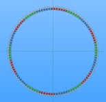
Miles said:I tried the winding calculator here http://www.bavaria-direct.co.za/scheme/calculator/ , to get a graphic of the phase layout, but it wouldn't accept more than 2 digits for the slot number :lol:
So, I've added it to the model. You can see the three symmetries.
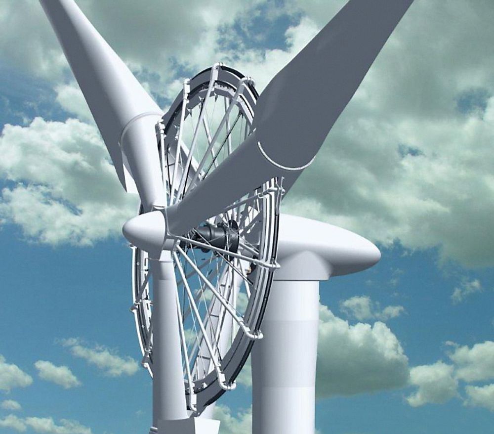
There's the Sineton design. That's two stator one rotor:Farfle said:I have seen a high specific torque motor with magnets on both sides of the iron. Essentially replacing the yolk iron with magnets, similar to the way a two rotor single stator axial flux motor works, but with radially configured flux instead.
Airgap area x airgap radius, the difference is 23 times. So, not so far off.....parabellum said:Do not forget, it got slimmer.Hillhater said:But we now have a motor with approx 10x the dia, similar weight of active materials, .so theoretically we ought to be expecting 10^2 ~ 100 times the Torque output..........but at the moment its only 16 times the Torque .?
Why this huge "orders of magnitude". difference ?
You marked it as cm, it does not mean centimetres right?Miles said:I've put the data onto the comparison spreadsheet.
I added a new column ( H ) for airgap area * airgap radius
Yes, that's the base unit. Sorry, that is confusing..Forgot to finish that off...parabellum said:You marked it as cm, it does not mean centimetres right?
The end turns are 40% of coil length, in this case.... We could certainly try keeping this configuration and reducing the diameter a bit to get a longer stack.toolbag said:The end-turn to useful copper ratio also gets pretty bad with a short stack motor like this.
In the Sineton introduction, that I posted above, they claim 40Nm peak torque per kg of active mass for their dual stator design (@ 170mm diameter, liquid cooling) and 10Nm per kg continuous torque for their claw pole design (@ 150mm diameter, passive cooling).toolbag said:The double rotor or double stator layout that Farfle mentioned gets you a little bit more torque per amp, and in an ideal world you can hope to see marginally more efficiency with one of those (on the order of 0.2% improvement on a 97% simulated efficiency). The trouble with those is that they suck structurally
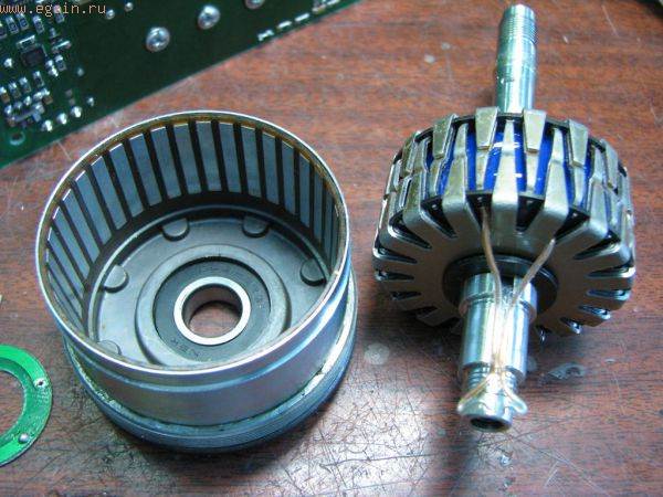
Miles said:https://www.indiegogo.com/projects/bimoz-the-world-s-smartest-e-bike-drive#/story
The Bimoz motor gives a maximum torque of 50Nm, for a 1.37 kg motor, according to the specification....
"Question:
"Direct drive systems like the BionX do have a drag torque when turned of like a traditional dynamo has when it’s turned on. Your system claims not to do so, how is that possible?"
Answer:
We took the term „direct drive“ serious in the development of the bimoz. The power transmission from the engine to the pedals takes place through an electromagnetic field. Our patented solution neither has gears, timing belts or other mechanical parts. Therefore it is a real direct drive. The powerful 250 W highefficient magnetic drive works electromagnetically. The result is no friction at all when you turn it off."