amberwolf said:
Apologies for derailing the thread...it wasnt my intention.

You didn't!
amberwolf said:
If it helps, they are each the MXUS 45H, a 4503 and a 4504. {snip:details}
Some math based on those details.
Mass: 1/4 ton (225 kg).
Speed: 20mph (32kph, 8.89m/s);
Time: 3 seconds.
Acceleration: 8.89 / 3 = 2.963 m/s²
Distance covered: 0.5 * 2.963 * 3 * 3 = 13.33 m
Energy required: 0.5 * 225 * 8.89 * 8.89 = 8,892 J.
Power required: 8892 / 3 = 2964 J/s.
Electrical power assuming 85% efficiency = 3.487 kW.
At 52V nominal, it would require 67 Amps.
With freshly charges (to 4.15V/cell) 58.1V = 60 Amps.
Your EIG C020 are rated at 20Ah, and 5C continuous, 10C max. < 10s, so with 2P you could theoretically be drawing up to 400A for your acceleration, which clearly points to your controllers as the limiting factor.
On the flip side, winding current only matches battery draw when WOT; (100%PWM). At lesser settings, the winding current -- and thus the torque -- can be substantially higher than the battery/controller are capable of delivering.
When PWM<100%, as the voltage is being pulsed, the average winding voltage over time, is less than the battery voltage. But Vbattery * Ibattery needs to be equal to Vmotor * Imotor; as the Avg( Vmotor ) < Vbattery, Imotor has to be higher to compensate.
I seen this alluded to here, but never a simple, cogent explanation of why. Of course, it gets complicated once you start factoring in the inductance into the equation.(You'll see why I mention this later.)
To achieve an acceleration of 2.963 m/s², assuming a 220mm rolling radius.
225 * 2.963 = 666.675N
Acting at 0.22m, gives 146.67 N.m
Of course, in the real world acceleration won't be constant, so you're probably delivering substantially more than that at the early stages. As the rpm increase, the torque dies away, but the power builds.
I thought about trying to work back from the specs for your motors
(Different model number, but the closest I found) to estimate the torque constant, but given two (and slightly different motors), different controllers, nothing by way of performance figures for the motors, and some hazily recollected data, I might just as well wet my finger and stick it in the air.
(Seems to be the done thing around here!

)
That brings me to regen; and how much force the motor acting as a generator can feed back via the stator to the axle.
There are 3 methods of producing a deaccelerating force (braking) from a motor
(Eg. 36V system with a motor capable of generating 45 volts and a 1Ω internal resistance.)
- Disconnect the motor from the battery and short the windings and use the motor's own resistance to sink the voltage generated.
Sometimes known as Dynamic braking; the generated voltage can also be shunted to a suitable external resistance.
The power dissipated is:
(45Vgen/1Ω)² * 1Ω = 2025W. (Effective braking)
- Feeding the generated voltage (BEMF, with its opposite polarity) back to the battery (+ve to +ve, -ve to -ve). (Charging regeneration.)
This is what one of your motors is doing.
Power dissipated (and hopefully, in large part captured) is:
((45Vgen - 36Vbat)/1Ω)² * 1Ω = 81W. (Gentle braking.)
- Using the the controler's bridges to feed the BEMF back to the battery +ve to -ve.
This is what the other of your motors is doing.
Power dissipated is:
((45Vgen + 36Vbat) / 1Ω)² * 1 = 6.561kW. (Hard braking.)
This is only sustainable for short periods; but if you're getting to 0 from your max. (cruising?) speed in <3 seconds,
then you'd be pushed to abuse it.
In reality, 1) and 2) coexist most of the time, with the Vgen flowing to the battery during the on pulse and back around the motor during the off phase, with the throttle controlling what percentage of which is happening at any time. Close the throttle for effective braking, but wasted energy, open it to put energy back into the battery, but only gentle braking.
I don't know if you recall one of our earlier conversations about regen; I was asking about the settings in my controller that talked about gentle/hard braking? I eventaully found the document with an explanation of the different forms regen can take, scanned it, but as my motor can't do regen, it was only of for the sake of knowing and I didn't expend any effort at that time to take it all in.
However, some of it stuck, because when Alan_B was getting uppity about why I was concerned about you trying my TA on the SBCruiser, I mentioned something about regen being capable of producing higher torque than driving the motor was capable of producing.
Of course, he poo-poo'd it.
(I envisage him as a General Melchett character, a reference you may not be familiar with, but
this will give you a flavour and
and this will explain the 'poo poo' 
)
I'm writing this whilst waiting for the 3D FEA of my TA to run; but its a free account to an online service which means they severely limit the rate at which jobs can run.
Add to that the 12 x 0.5mm spring layers + frame and nut, and the 13 low-micron (surface irregularity) component interfaces which are an inherent frictional part of the design, and the mesh has to be very fine, so produces a huge number of tetrahedrons. It ran for 9 hours before telling me that it didn't like the way my CAD system structure the data, and ended in failure.

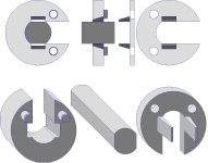
BTW. I have another novel design that addresses some of the issues raised and was prompted in part by your far greater energy and torque requirements detailed above:

The two C-shaped parts are design to fit around the axle and then slot together, with the wedge shaped prongs on one, fitting into wedge-shaped slots in the other. As the nut is tightened, the wedge act to clamp the pair securely to the axle flats.
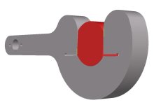
The arm -- not shown -- is another multi-layer edgewise cantilever beam affair, that is attached to the frame with a single, pivot screw.
The two slotted C-parts are fixed to the axle and then the swiveling spring arm clicks into the slot in the thicker C-part with a positive action that needs a small lever -- screwdriver, coin -- to release it.
In this way,
- the axle is protected from impact damage by the clamping action of the wedges;
- the wheel is positively located should that hoary ol'chestnut of the wheelnuts being stolen (but the motor is left behind
 )
)
comes to pass, but
- releasing the wheel for roadside puncture repair is easy, using minimal tools beyond those you would need anyway.
(Keep the nail from your first puncture and you can use it to release the TA then next time  ).
).
- the design again seeks to supplement rather than supplant the existing dropout, and use spring energy to absorb
and return the torque snap energy, rather than just butting heads with it.
The downside is complexity -- which is also cost -- but I have a few ideas about how to simplify it.
Enough's enough. I just heard a ding, which either means my sim has finished or failed or I left something in the microwave and forgot about it.
If I succeed in posting this despite half my previews being discarded, apparent temporary blacklisting -- "endless-sphere.com failed to return any data" -- and all the other ab .. er, anomalies, but don't get back for any reason, feel free to use it, or poo poo it as you see fit

Buk


