throttle replacing problem

motornews

1 W
Joined
Jan 26, 2011
Messages
53
Location
serres greece
hi to everybody
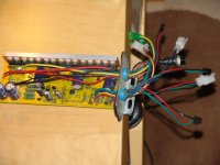
broke my throttle in my chineze ebike kit.from then on i got 5, yes five, new ones and can not connect them.dif number of wires and dif colors.
its so hard to see your marvelous E BIKE and cant take a ride with it.
infos-my mother throttle was with on-off button,three lights for the power meter and had total 7 wires.
the controler is ok as the technician says.if i make a conection the motor starts at fullvolts(48v-1000w front w.)
but the most interesting thing is that as i grab the wires at the conection spot(where they are glude)the motor starts.( always on stand)
original throttle was with a half cyrcle magnet.
thanks in advance
 
Hi and welcome to ES.

If you could post photos of the throttles you have, showing the wire colours, we could probably help sort out which wire goes where.

Standard throttles have three wires, usually red for +5V, green or blue for the throttle voltage output and black for 0V.

Throttles that have battery indicator lights usually have four wires, three being similar in colour to those above for the three wire throttle (although not always) and a fourth wire than is at the battery voltage to run the indicator.

It sounds like you may have a throttle with the three way speed selector switch, as they have around 6 or 7 wires.

Any more information you can give would help a lot.

Jeremy
 
thnks for the sort notice
1st its the controller pics
the the last throttle that ive got ,similar with my first one but one wire sort (6 the original had 7)and the wires of the throttle.
very nice forum.i will talk about it
thanks again
ps.i made the bike on octomber i run it for two days and then i broke it.from then i am ordering throttles.xexe
 

Attachments

  • DSC07360.JPG
    DSC07360.JPG
    31.5 KB · Views: 2,044
  • DSC07364.JPG
    DSC07364.JPG
    42.7 KB · Views: 2,044
OK, thanks for those pictures.

I'm going to make an educated guess as to which wire goes where. The important throttle wires are the red, green and black ones. I believe that the white connector from the controller is most probably the main throttle connector. If you have a multimeter or voltmeter, then measure the voltage between the red and black wires (red positive, black negative) on the controller throttle connector with the controller powered but without the throttle connected. If this is the throttle connector, then you should get a voltage of between 4.5 and 6V or so between the black and red wires.

If this is the case, then connect the throttle wires so that the red goes to the red, the green to the green and the black to the black on this connector. This should make the controller work, but the other functions of your throttle (the LEDs etc) will not work.

If you don't get the right voltage between the red and black wires, come back here and we'll have another go at trying to help.

Jeremy
 
hi jeremy
sorry friend nothing hapened
the voltage as you said was 4,8v bat conected no throttle,red-black
bat voltage in 50,8 i thing its ok.
and iam having full run of the motor wheel at full speed in one conection(dont remember witch wire whent where).but if it is important i will trie it to verify the colors.
 

Attachments

  • DSC07369.JPG
    DSC07369.JPG
    40.6 KB · Views: 2,031
HI JEREMY
when i conect --- I red-black I
controlerI green-green I throttle
I black-red I
then the motor wheel goes full speed,WITHOUT PRESSING THE THROTTLE(throttle at idle)
NOW WHAT?
 
motornews said:
hi jeremy
sorry friend nothing hapened
the voltage as you said was 4,8v bat conected no throttle,red-black
bat voltage in 50,8 i thing its ok.
and iam having full run of the motor wheel at full speed in one conection(dont remember witch wire whent where).but if it is important i will trie it to verify the colors.

The fact that you have +4.8V on the red wire and 0V on the black wire is good, as it shows that these are the throttle power leads. Next we need to work out which is the throttle voltage input. First, connect just the red and black leads to the throttle, with no other wires connected, making sure they are the right way around, or else you risk blowing the throttle up.

Then measure the voltage from the other wires coming from the throttle, not the controller, as you turn the throttle. One of the wires should increase in voltage as you turn the throttle, this will be the throttle output wire.

Once you have found out which wire has the throttle voltage on it, then this is the wire that should connect to the controller green wire on that white connector.

Jeremy
 
take a look at the pics, hopefully this will help.

i also included a pic of one of my throttle hall sensors so you can see it up close,
it uses red (pos), black (neg) & white (variable)


DSC07369[1].JPG

P1070002.JPG
 
ok white is ground, thought that other picture was your controller. but it may be ruined already if it was reversed. maybe someone who knows about these linear hall sensors knows. it is the equivalent of the honeywell SS495 i expect from the label.
 
dnmun said:
ok white is ground, thought that other picture was your controller. but it may be ruined already if it was reversed. maybe someone who knows about these linear hall sensors knows. it is the equivalent of the honeywell SS495 i expect from the label.

No. Black is ground, white is the output. These devices have the output on the end and the ground wire in the centre (see the attached datasheet).

Jeremy
 

Attachments

  • Hall throttle sensor datasheet.pdf
    151.9 KB · Views: 85
Looking at the above posts/info and the link below appears to indicate the following connections:

Throttle Red wire (4.8v, hall sensor) = Controller (white connector) Red wire

Throttle Black wire (ground, hall sensor) = Controller (white connector) Black wire

Throttle White wire (variable voltage, hall sensor) = Controller (white connector) Green wire


http://docs.google.com/viewer?a=v&q=cache:upv-9VvI1eUJ:www.goldenmotor.com/e-Bike-DIY/Cruise%2520Controller%2520Wiring%2520Diagram.pdf+Golden+Motor+controller+wiring+diagram&hl=en&gl=us&pid=bl&srcid=ADGEESh66gNaERV5k3ly61kphc1x8aJ7b1QKLqcx45DOuDcFLQy-SjJz2ZLpdr9iaDV80n3lyHB3Bna9lzflB_XvS5u5gmc57I4qFUGTzBEhiX3NXCB6uFQjiC7K2FixFnAHolVfcq7Z&sig=AHIEtbRDg7kzVHLV1_O4JNctW-hRtKVyzQ

The problem is that the controller and/or throttle may have been previously damaged.
 
thanks to all of you first of all.
i made both ways but nothing hapens
fmb42-this was my first attempt -and i noticed that the name of the throttle co,its golden motor co.but diferent controller.
jeremy -after connecting red and black,no other wire delivers volt,after throttleing.(these 2 wires when connected are producing at idle 4,8v)
i supose that meens that the hall sensor its 'previously damaged'(cause iremember a big spark when trying at first,and not the spark when connecting the bat cable)
so if i need new throttle (my 6th) dont be shy and tell me so..xexe
thanks
 
I was thinking that you have a Golden Motor system by the looks and wiring of the original throttle assembly. The GM "magic" controller shown in the link I provided is indeed different from your controller. However, the wire color/connections are the same as found in my standard "non-magic" controller GM kit.

The problem is that your system could have had more than a damaged throttle from the very beginning (when it first "broke down"). More damage could have been done during the trouble shooting "testing". This is, unfortunately, part of the risk we take when working with electrical/electronic circuits and systems. This "risk" is even greater due to the fact that GM and many other ebike kit manufacturers often offer little or no reliable information in regards to troubleshooting their systems (some, in fact, don't even offer a competent assembly guide). Believe me, most of us have been through what you're now experiencing.

You could, at this point, have a damaged throttle, controller, and/or motor. Having said this, I would double check the following:

The battery (make sure it's fully charged).

The system fuse or fuses (every ebike system should have at least one fuse for the main system and, in some cases, another fuse for the Battery Management System or "BMS" ).

For damaged wires (i.e. burnt, cut, or pinched wires and/or wire insulation).

The wire connections (make sure that all connections are clean and tight, etc).


Another troublesome problem with electrical/electronic troubleshooting is the fact that one "bad" system component (i.e. the throttle or controller or motor, etc) can damage another component which, in turn, can damage another and so forth. This can often result in having no choice but to replace all of the system components at exactly the same time.
 
i am reading that you must have a fuse between bat and motor!xexe..i bypassed it ...yuppiiiiii.
so i thing after some big sparks i had somethig burned.so...
begining---
i sould replace controller and throttle as one buy (same seller) so can work together.
cause the motor is runing at full,(when iconnect the red controler-black throttel+red throttle-black controller).
OR ELSE???
ANYBODY??
recomendations?
 
Hi motornews,

You should have your hub motor tested before you attempt to replace the controller and throttle assemblies. You can have a qualified E-bike shop do this for you or, you can test it yourself by carefully following the test proceedures below:


1. Test the hub motor windings. You should have an resistance reading of ~0.4 ohm across any 2 of the 3 hub motor phase (winding) wires. These phase wires are the heavy gauge Green, Blue, and Yellow wires running from the hub motor (as shown in the Golden Motor wiring diagram). Be sure to test every phase wire "combination" during these tests.

Note: Any ohm readings above or below ~0.4 ohms could indicate an open or shorted motor windings. Warning: do not attempt to connect your controller/throttle/battery to any hubmotor that indicates open or shorted motor windings . Doing so may result in a damaged controller, throttle, and/or battery.

You should also have an infinite (open) ohm (resistance) reading between any 1 of these 3 phase wires and the motor case. Again, be sure to test every phase wire "combination" during these tests.

Note: continuity between any phase wire and the motor case indicates a "shorted to ground" motor windings. Warning: do not attempt to connect your controller/throttle/battery to any hubmotor that indicates a "shorted to ground" motor winding. Doing so may result in a damaged controller, throttle, and/or battery.


2. Test the hub motor "hall effect sensors" (located inside of the motor case). You should also check the hub motor "hall effect" sensors as per the test proceedures found in the link below:

http://www.endless-sphere.com/forums/viewtopic.php?f=2&t=8041&start=0


motornews said:
i sould replace controller and throttle as one buy (same seller) so can work together.

This is often a good idea. It can also, of course, be a good idea to replace the controller and throttle with Golden Motor units that are designed to work with your existing GM hub motor. Otherwise, I would try to find a replacement controller and throttle that includes the necessary wiring directions needed for use with your particular Golden Motor kit.
 
i am about to order a controller for my e bike.this one.http://www.electricscooterparts.com/hookup/SPD-481000Bwiring.htm
is ok with my throttle and motor?
can enyone tell me?
thanks
ps..(48V 1000W Electric Scooter Speed Controller
Designed for 48 Volt DC motors up to 1000 Watts. Maximum current 30 Amps. Under Voltage protection 41 Volts. Current limiting feature prevents controller and motor damage due to over-current conditions. Under voltage protection feature prevents over-discharge and extends battery life. Uses standard 3-wire variable speed hall-effect throttle.
item # SPD-481000B)--http://www.electricscooterparts.com/speedcontrollers48volt.html
 
i took some pics so mayby somebody guide me to MAKE THE CONECTION
or make the test to see what is dead and what not!!!!!!
(the 2 wires of the hubmotor have 4,8v each-so i thing the motor is alive)
 

Attachments

  • DSC07373.JPG
    DSC07373.JPG
    48.7 KB · Views: 1,681
  • DSC07375.JPG
    DSC07375.JPG
    52.3 KB · Views: 1,681
  • DSC07379.JPG
    DSC07379.JPG
    60.9 KB · Views: 1,681
  • DSC07380.JPG
    DSC07380.JPG
    62.8 KB · Views: 1,681
FINALLY i ordered a controller-throttle together from golden motors
and i am on the streets again
probably i had damaged the above units...both
120 usd gave me the happiness of riding again
 
Back
Top