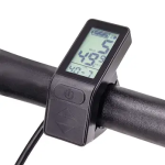
It is this display and I doubt there is much space in the case. Maybe I can get away with thin enameled wire, as used in transformers, and just add a shrink tube outside of the case...
If it's the one pictured below, there's probably quite a bit of space around the buttons, though you have to make sure the wire doesn't interfere with the buttons themselves if you still want the built-in ones to function easily. If you have any unused USB cables (or devices with them built in) laying around, you can probably use the very thin wires these use to fit right in there. There will be at least five wires in any good USB cable--red 5v, black ground, green / white data lines, and a probably uninsulated shield wire. Some cables have more wires in them (though they may be unconnected at one end or the other). Apple Lightning cables are similar.
If you don't ride in the wet (or can waterproof the connection) you could even install a port on the case of the display so you can unplug the button module for whatever reason.
Just in case you are interested what I am doing, I have written a little bit of
project documentation in a german forum... I am pretty sure google translate will give a somewhat good enough translation.

Thanks! I'll go read up on the project, it might help me give you better suggestions.

(or at least ask better questions).
I don't want to connect the HD with the CA. They are completely unrelated, but I would like to remote control HD and also the display.
Ok, I guess there is some missing info from your original statement I replied to about that, since that statement implied you wanted to build something like the CA that would let you remote control the Karoo (HK)...but the CA doesn't remote control anything.

For the remote contro
It is this display and I doubt there is much space in the case. Maybe I can get away with thin enameled wire, as used in transformers, and just add a shrink tube outside of the case...
If it's the one pictured below, there's probably quite a bit of space around the buttons, though you have to make sure the wire doesn't interfere with the buttons themselves if you still want the built-in ones to function easily. If you have any unused USB cables (or devices with them built in) laying around, you can probably use the very thin wires these use to fit right in there. There will be at least five wires in any good USB cable--red 5v, black ground, green / white data lines, and a probably uninsulated shield wire. Some cables have more wires in them (though they may be unconnected at one end or the other). Apple Lightning cables are similar.
If you don't ride in the wet (or can waterproof the connection) you could even install a port on the case of the display so you can unplug the button module for whatever reason.

Just in case you are interested what I am doing, I have written a little bit of
project documentation in a german forum... I am pretty sure google translate will give a somewhat good enough translation.

Thanks! I'll go read up on the project, it might help me give you better suggestions.

(or at least ask better questions).
I don't want to connect the HD with the CA. They are completely unrelated, but I would like to remote control HD and also the display.
Ok, I guess there is some missing info from your original statement I replied to about that, since that statement implied you wanted to build something like the CA that would let you remote control the Karoo (HK)...but the CA doesn't remote control anything.

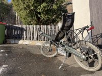
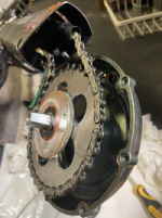
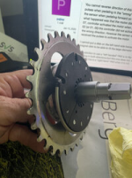
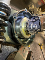
As you can see, the chain is internally with this bike. Also the motor is a front wheel one, hence there is no way to detect the pedaling torque there...
And for the PAS, I have
a custom solution due to the frame.
Well, the CA does a great job even with just a cadence sensor like you installed inside the housing,
of variable control of the system via cadence. (like I do on my SB Cruiser)
If you have situations that require the motor to run before you can pedal (like getting started from a stop while pointed up a steep hill), a torque sensor would be the "best" solution to that. But the *easiest* solution is a "go button" you can press for a specific amount of throttle (or the actual throttle) just to get started and then use the PAS by pedalling normally.
The only "easy" way I can think of ATM to use a torque sensor on that type of system is one that rides on the chain, like the no-longer-available BEAM TS did, so it detects tension on the top of the chainline and outputs a proportional voltage to that. From what I can see of the system you would have to cut a hole on the top of the chain housing for the guide wheel of the sensor arm to ride on the chain, and presumably print a housing to cover that unit. It can be anywhere on the chainline, wherever is out of the way...but I don't presently see another option for this.
Well, there *are* sensors for bike training that go on (or replace) your pedals / crank arms, and wirelessly transmit their data to their system's main unit...so you could either build a clone of such a sensor or buy one and then either replace the transmitter with one of your own or figure out their protocol and data format to read it with your own system, that then creates a throttle signal (or creates a 0-5v signal to feed to a Cycle Analyst v3 to let *that* create such a signal).
It would be nice to remote control the display to change the power of the motor. The display is mounted on the left side of the handle bar just below the grip now. It's hard to see, as it's black...
I currently use a (now nearly ancient) Suunto Ambit 2 to record my rides and to monitor my heart rate. But I always forget to start or stop the watch. Also uploading the activity recordings to my computer is a bit annoying. In opposite the HK is always directly in front of me and I never forgot to start or stop an activity when I used it. Also it connects to my home WiFi and uploads the activity as soon as I stop the recording... Makes it really trouble free.
It's just impossible to reach the HK when it's mounted just behind the front light, right there where there is a little bike computer now.
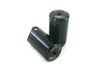
FWIW, a simple mechanical solution to pressing buttons (that works on touch screens or on mechanical switches) is to use an air button. It's a button (that looks and feels like the buttons on an arcade game machine console) that has seals in it to push some air thru a tube to push on some remote thing; they're commonly used in aquatics systems since wires corrode but these don't.

Garbage disposal switches mounted on sinks also use a variant of them.
Often they're used by routing the air tube out to a "normal" electrical switch that's operated by this tiny amount of air pressure, but they can also be used to push a "reversed" mechanism that pushes a rod out a tiny bit with the air's force, to press another button on something else.
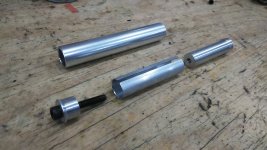
The nifty thing is you could design and print both of those parts instead of trying to find ones that fit your specific application, and just use regular rubber O-ring seals on the moving parts to keep the air between them / in the tubing, and use stiff-walled tubing (1/4" diameter is easy to find and is usually used) between them.
Then you mount the button on your bars and the remote pusher on the face of the device, with a touch-screen stylus's tip on the end of it to touch the button on the screen of the device. The primary disadvantage to this is it covers that portion of hte screen, but a properly designed one would only cover the amount of screen necessary to hold the stylus tip over the button.
Hope this clarifies everything a bit.

It does, and your thread over there will probably clarify more.


