
Astropower
10 mW
Hello folks,
I got two TOSEVEN DM01 1000W 52V, with LCD135C display.
In order to serve the community, i am posting here the manual of TOSEVEN LCD135C Display manual. Which sent by the Factory.
The factory did not write in the LCD135C manual, how to get in the Advance Menu and FOC Menu, so i took it from the T24 manual, and put it together in one file.
And Firmware update for this display, from 21/06/2024
Instructions how to program:
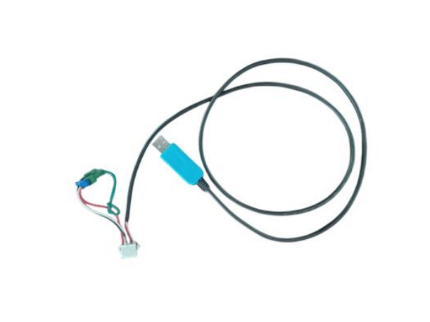
 to7motor.com
I got two TOSEVEN DM01 1000W 52V, with LCD135C display.
In order to serve the community, i am posting here the manual of TOSEVEN LCD135C Display manual. Which sent by the Factory.
The factory did not write in the LCD135C manual, how to get in the Advance Menu and FOC Menu, so i took it from the T24 manual, and put it together in one file.
And Firmware update for this display, from 21/06/2024
Instructions how to program:
Program Updating Instructions
Explore our guide for e-bike controller and display program updates. Detailed, step-by-step instructions for enthusiasts and professionals
to7motor.com
