jamiejackherer said:
Firstly, I did test the voltages in each cell, and each cell was testing at 3.76v.
Under load, or just sitting there not connected to the controller? If under load, what is the exact current reading (amps)?
(the complete conditions of a test need to be stated along with the results, or the results aren't useful to help you without making more assumptions that have a high probability of being wrong.)
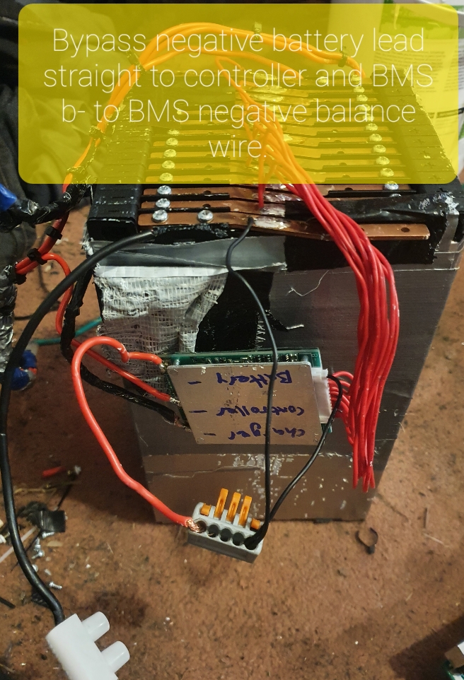
Also the voltage is not sagging much at all, in fact with the BMS it would sag from 54.1v (full charge) to 49.9v, and at 47v it would sag to 44v. After bypassing the BMS it sagged from 51v to 50v under high load!
What exactly is "high load"? Is it the same exact load that the other voltage measurements were done under? (it's not possible to compare the one to the other directly if the load is not the same. If it's different, then one can only make assumptions about the differences in behavior, unless the entire range of behaviors at varying loads is characterized and graphed.)
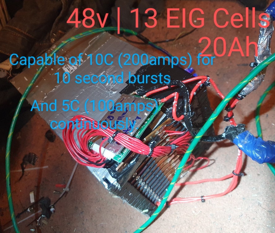
Because I am not using 18650's and I am using lithium polymer cells my low voltages are a little different. The cells have a recommended low voltage of 3.0v per cell so that's 39v for my 13s battery. But, the cells are capable of discharging to 2.5v which is 32.5 for a 13s. The BMS would LV cut off at 41.3. I have a voltmeter throttle so can keep an eye on the battery voltage.
You can discharge any cell to a lot lower voltage under carefully controlled lab conditions (which is what spec sheets are written from; many spec sheets also give those conditions but some don't) than you can in actual usage situations. Also, those cells tested to those conditions aren't typically expected to be used for the same number of cycles that you would expect to get out of a pack in actual usage.
However, the main problem with using an LVC below the "recommended" voltage is that it is a lot harder on the cell to do that. Typically, the higher they are charged to, and the lower they are discharged to, and the more often these are done, the faster any particular cell's capacity and capabilities degrade.
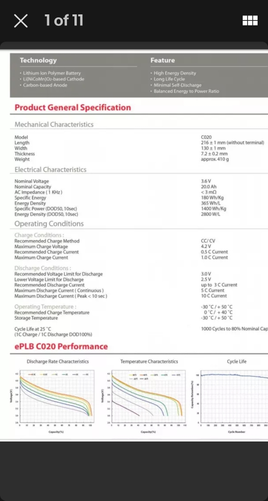
I also know the technical data for my cells very well.. the high voltage for my eig cells is 4.2 not 4.15 (see spec sheet in pic) .
I've been using the same cells (EIG C020 NMC 20Ah, right?) for about a decade on three different ebikes (one medium-cargo bike, one light-cargo trike and one heavy-cargo trike), so I have a tiny bit of experience with them. It's possible it is not as much as you have, but I will make the assumption
")
that it is significantly more.
Given the image you posted, I did a bit of poking around.
I've attached the PDF spec sheet from EIG for these cells, where it specifies the maximum charge voltage as 4.15v. So maybe EIG has two different specifications for the same cells, implying either they revised the spec in light of new data that neither of us has (I don't know which spec is newer) or they have two (or more) versions of these cells and one of these applies to one version, and one to another...but there's no data on them to say which would be which.
EIG doesnt' appear to be still around to ask
https://www.komachine.com/vi/companies/eig/
says "this manufacturer closed down"
with the WM's last archive from about 2013 indicating it's been quite some time, but I found a version of their pages on the wayback machine:
https://web.archive.org/web/20130407092202/http://www.eigbattery.com/
Since it uses flash, I can't get a direct link out of that, but if you click the Cell picture in teh scrolling display, it gets you to the page where I long ago got the same spec sheet that I attached (though the one taht's attached came from the Ebaracus site since that was easier than locating the actual file I have on my system). On that new page clicking the C020 download column link gets you a jpg version of it
https://web.archive.org/web/20130408041849fw_/http://www.eigbattery.com/eng/product/3.jpg
The other site
https://www.komachine.com/vi/companies/eig/products/56934-C020/
doesn't have the complete specs, but those it does have match the archived EIG sheet.
I didn't search for very long but I couldlnt' find a version of the spec sheet that looks like the pic you posted, to see if either had publication date or other info on it that would help figure out what the right specs for these cells are.
I do note there are some significant discrepancies between terminology and numbers on some parts of the one from the other, such as the second Energy Density listed on your image, which seems to correspond to Power Density on the spec sheet from the EIG site archive. I'm not sure if it's just a typo on one sheet or the other, but I suspect it's correct on the EIG archived version simply because the units aren't what is used for Energy Density, but are for Power Density.
My personal suspicion, based on experience with released spec sheets vs preliminary spec sheets, is that the pic you have is from the latter, and the archived (and attached) version is the former, so that the cells actually out there are supposed to be used with the version as attached. Given that it is more conservative, it's safer to go with that, so that's what I'll continue to do.
Why, exactly, they give either number, I don't know, as I am not a battery chemist.
But this is what they spec'd their cells to operate at in the spec sheet I've always run across (as attached), so that's what I use them at, because other people have run other cells meant to be used in a lower voltage range at higher ranges, and gotten less useful life out of them than they should have based on spec sheet expectations...and probably would have gotten the full life if they hadn't "overcharged" them.
There's not enough energy in the portion up there between 4.1 and 4.whatever to make enough of a difference in capacity between 4.15v and 4.2v, so if given the choice between a teensy bit more capacity and a potentially significantly longer lifespan, I'll pick the latter.
So, you can use your cells at any voltage range you prefer, as they *are* your cells. And I will continue to use mine at less (4.12 is what mine charge to with my present 14s2p pack on the SB Cruiser trike).
you are both assuming a lot and wrong a lot
I have to assume a lot because most people that post here don't post complete info, and won't answer questions completely (if at all). After years of trying to help people here with incomplete info, I've given up on expecting it, and learned to just accept that some people wont' like my style of help, but to go ahead and help them anyway by making the necessary assumptions to post conclusions that might set them on the path to fixing their problems. It's ok with me if you don't like it, either--I'll still help as much as I can, unless you prefer me to stay out of your threads...but all help (from anyone) will still be full of assumptions until you provide all of the necessary data to not have to do so.
And anything based on assumptions is bound to be wrong a lot.... But it is what I can do with what's provided so far.
One example of this that happens frequently with all sorts of problems people post here: if the results of tests that are suggested aren't provided, then anyone reading has to assume either the tests weren't done, or that if they were done they wont' have any idea what they were. Thus they have to either drag that info out of the person with the problem, or just make assumptions and suggest further tests or potential problems that are based on the info that *has* been provided.
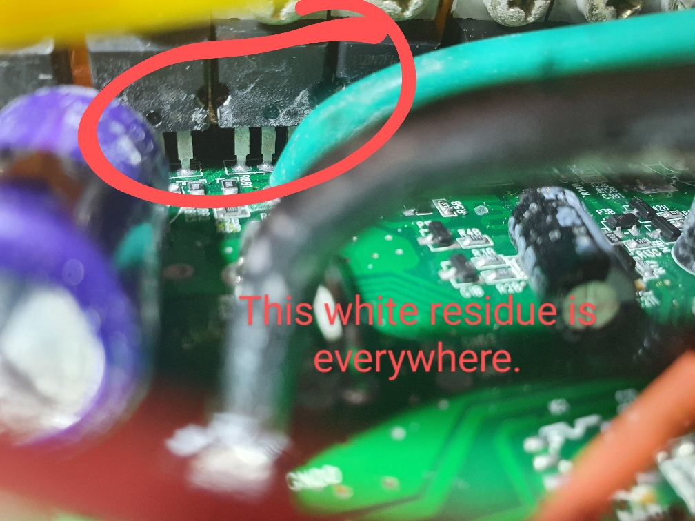
Since everything you've provided so far points to a problem with voltage sag, as the symptoms described for both BMS and controller are all exactly that kind of result and cause, then without those voltage results (some of which you've now provided but only a little with context of some test conditions, but not all test conditions and not for all results) the only thing I can do is assume you have a battery problem, or that you have a connection problem (and the voltage is dropped across that).
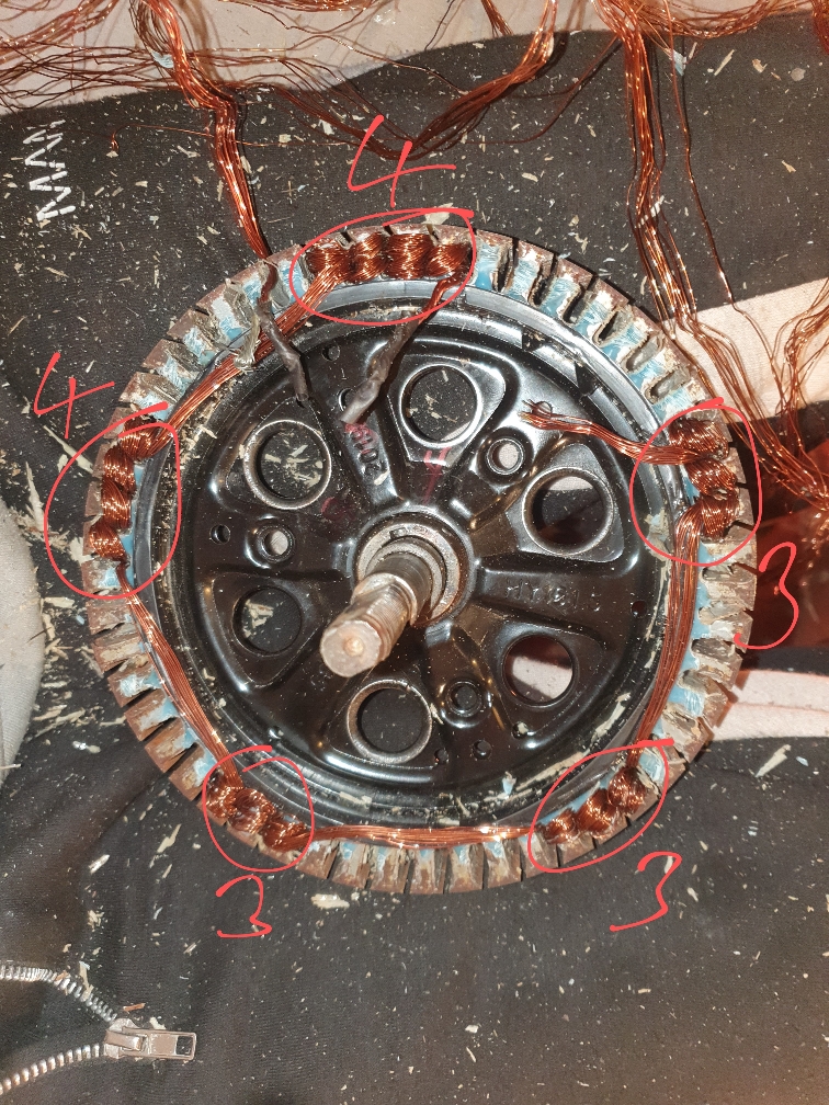
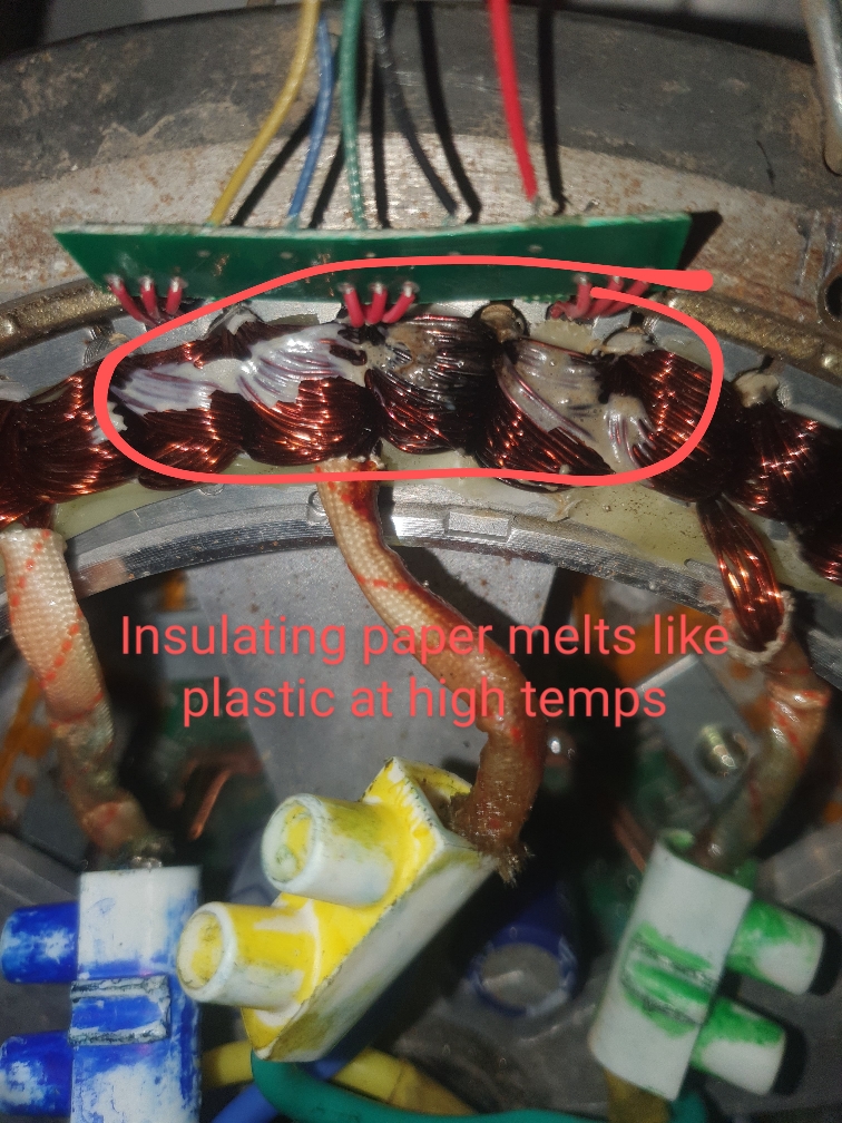
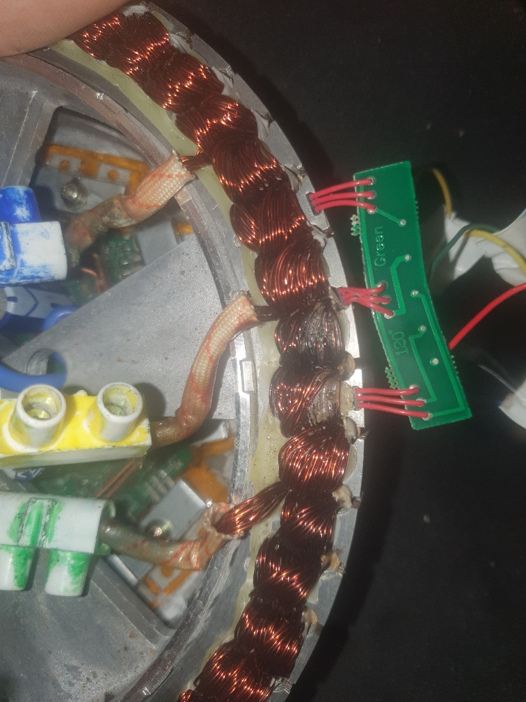
Since a connection problem dropping that many volts would be really hot, and possibly smoking or at least melting or deforming insulation or plastic around it, it is a fair assumption that it's not a single-point connection problem. But I still have to make assumptions...because the data provided is not complete.