
I keep getting error 07 on my EKD01 display with the newest OSF at test6_with_pll firmware, despite having the same settings from the previous releases - battery parameters, limits are all set. It mainly happens under load. Other than that, it feels promising

-
Hello ES! We could use some help to get us past the finish line on building the new knowledgebase for the forum.
Can you donate? Please see our fundraising page. Thank you!
You are using an out of date browser. It may not display this or other websites correctly.
You should upgrade or use an alternative browser.
You should upgrade or use an alternative browser.
TSDZ8 OSF (open source firmware)
- Thread starter mstrens
- Start date
I'm having the same problem with the e07. The settings are the same as the existing Spider firmware. After testing, I realized I had set the maximum motor power to 1000W and the maximum current in the battery menu to 20A. The error also pops up under load. I thought maybe the error pops up because with a charged battery (48V battery) the power exceeds the 1000W I set as the maximum motor power. I haven't had time to test anymore, but if I lower the current so that it doesn't exceed 1000W, or increase the maximum motor power, maybe the problem will be solved? I'm using the SW 102 display.
This error is generated when the current exceeds the max value + some margin.I keep getting error 07 on my EKD01 display with the newest OSF at test6_with_pll firmware, despite having the same settings from the previous releases - battery parameters, limits are all set. It mainly happens under load. Other than that, it feels promising
There is a parameter "overcurrent delay" that can be changed. By default, it is on "2" (I think). It means that the limit could not be exceeded during 2 * 25 msec = 50 msec. You can try to increase the default value to e.g. 5 (=125 msec).
If you set the value on 0, the check is totally discarded.
At least , this is the case in main branch version.
In the test6 version, this is still valid but I also added some more checks that could generate this error.
Important note: change this at you own risk as a huge current can destroy the controller.
Then, the error results of the new checks that I added.The overcurrent delay was set to 0 (which supposedly removes the error), and I still got error 07 despite that
If you want, I can make a version that avoids this check or if you compile your self, I can explain the parameters that could be increased.
I'd appreciate if you could explain what checks you added. I only compile within JavaConfigurator, am unexperienced otherwise - I think you meant compiling the rest, so if you could also make a version without those checks would also be great
I rode my bike today with the 860C_SPIDER_3_V00_02.01 firmware, and the motor worked very smoothly. I liked it very much.
However, the motor continued to assist occasionally after I stopped pedalling. The assistance remained on for between one and five seconds. Occasionally, I turned it off by pressing the brake.
Perhaps my Torque adc offset value is too low.
I will check the values tomorrow and make the necessary adjustments.
However, the motor continued to assist occasionally after I stopped pedalling. The assistance remained on for between one and five seconds. Occasionally, I turned it off by pressing the brake.
Perhaps my Torque adc offset value is too low.
I will check the values tomorrow and make the necessary adjustments.
Indeed, most likely, you have to change the adc offset value.I rode my bike today with the 860C_SPIDER_3_V00_02.01 firmware, and the motor worked very smoothly. I liked it very much.
However, the motor continued to assist occasionally after I stopped pedalling. The assistance remained on for between one and five seconds. Occasionally, I turned it off by pressing the brake.
Perhaps my Torque adc offset value is too low.
I will check the values tomorrow and make the necessary adjustments.
In version 0.2.xx, I also measure each of the 3 currents between each low side mosfet and ground and I check that they do not exceed some values.I'd appreciate if you could explain what checks you added. I only compile within JavaConfigurator, am unexperienced otherwise - I think you meant compiling the rest, so if you could also make a version without those checks would also be great
Here is a version (for vlcd5 (and similar) display where I disabled those checks.
The original check from 0.1.XX version based on the total current is kept but can be disabled setting
overcurrent_delay on 0.
Use it at you own risk.
Attachments
No there is no real change.Lately I have been riding all the time with OSF_TSDZ8_860C_SPIDER_3_V00_01.35.hex.
To start testing the new OSF OSF_TSDZ8_860C_SPIDER_3_V00_02.01.hex, do I need to change anything in the 860C display settings?
Still In previous version, it was possible to specify the foc multiplier from the display reusing a field named coast brake threshold. This version does not use anymore the foc multiplier because the best lead angle should be calculated automatically.
Therefore, I reuse the field coast brake threshold in order to monitor how lead angle is now calculated.
The lead angle is now the sum of several parameters:
- a part depending on the motor speed (rotation per min); this part increases when rpm increases. The relation is not linear and use a table with severals entries. This part can vary from 0 up to 14° (with existing set up)
- a part depending on the battery current; this part increases when current increases. The relation is linear in this firmware. This part can vary from 0 up to 15° (with existing setup).
- the sum of those 2 parameters makes the "base lead angle". It is calculated at quite high frequency. If the parameters used in the calculation are good, the base lead angle should be very closed to the best value.
- In order to further optimise (and to compensate some deviations in the used parameters), OSF calculates a correction. This correction is calculated in order to minimise the "unproductive" current (usually named Id in FOC algorithm). This correction can vary from -5° up to +5° (or perhaps from -10° up to +10° - I do not remember). It is adapted much slowlier the base lead angle.
Ideally the correction should remain quite small. If it is not the case, it means that the parameters used for based lead angle are not good enough.
I made some tests with a trainer to set up some parameters but I am not sure they are the best one specially for high current.
In order to check the result, I reused the field named coast brake threshold from the display in order to let the user selects which lead angle must be displayed as FOC angle.
Here the values you can fill in coast brake threshold
// 10 = total lead angle,
// 11 = part of base lead angle depending on rpm
// 12 = part of base lead angle depending on current
// 13 = base lead angle (sum of 2 parts)
// 14 = correction based on Id
To check if the parameters used curently are good, you could set coast brake threshold to 14 to display the correction
On the 860C, you can then display simultanously RPM, battery current and FOC.
You can check that FOC (= correction) remains quite small (e.g. between -5° and +5°).
If it is not the case, when the values are stable, note the set of 3 values (RPM, battery current and correction) for different RPM and current. This would allow to further adapt the parameters I predefined.
Important note: 860C can't display negative values but correction (and so total lead angle) can be negative. To solve this issue without changing the 860C display firmware, OSF will display negative value above 200. So 201 means -1°, 202 means -2°, 203 = -3° etc...
thank you very much for the detailed technical explanation.No there is no real change.
Still In previous version, it was possible to specify the foc multiplier from the display reusing a field named coast brake threshold. This version does not use anymore the foc multiplier because the best lead angle should be calculated automatically.
Therefore, I reuse the field coast brake threshold in order to monitor how lead angle is now calculated.
The lead angle is now the sum of several parameters:
- a part depending on the motor speed (rotation per min); this part increases when rpm increases. The relation is not linear and use a table with severals entries. This part can vary from 0 up to 14° (with existing set up)
- a part depending on the battery current; this part increases when current increases. The relation is linear in this firmware. This part can vary from 0 up to 15° (with existing setup).
- the sum of those 2 parameters makes the "base lead angle". It is calculated at quite high frequency. If the parameters used in the calculation are good, the base lead angle should be very closed to the best value.
- In order to further optimise (and to compensate some deviations in the used parameters), OSF calculates a correction. This correction is calculated in order to minimise the "unproductive" current (usually named Id in FOC algorithm). This correction can vary from -5° up to +5° (or perhaps from -10° up to +10° - I do not remember). It is adapted much slowlier the base lead angle.
Ideally the correction should remain quite small. If it is not the case, it means that the parameters used for based lead angle are not good enough.
I made some tests with a trainer to set up some parameters but I am not sure they are the best one specially for high current.
In order to check the result, I reused the field named coast brake threshold from the display in order to let the user selects which lead angle must be displayed as FOC angle.
Here the values you can fill in coast brake threshold
// 10 = total lead angle,
// 11 = part of base lead angle depending on rpm
// 12 = part of base lead angle depending on current
// 13 = base lead angle (sum of 2 parts)
// 14 = correction based on Id
To check if the parameters used curently are good, you could set coast brake threshold to 14 to display the correction
On the 860C, you can then display simultanously RPM, battery current and FOC.
You can check that FOC (= correction) remains quite small (e.g. between -5° and +5°).
If it is not the case, when the values are stable, note the set of 3 values (RPM, battery current and correction) for different RPM and current. This would allow to further adapt the parameters I predefined.
Important note: 860C can't display negative values but correction (and so total lead angle) can be negative. To solve this issue without changing the 860C display firmware, OSF will display negative value above 200. So 201 means -1°, 202 means -2°, 203 = -3° etc...
Now it is clear to me how the base lead angle is built from the RPM-dependent and current-dependent parts, and how the additional correction (Id-based) is slowly adapted on top of it. Reusing the coast brake threshold field as a selector for the displayed lead angle / correction is also a very clever solution.
This approach makes a lot of sense from a control and efficiency point of view.
If the base lead angle is already close to optimal and the correction remains small, the motor should run with better FOC alignment, which in practice can mean smoother operation, higher efficiency and potentially lower current consumption for the same mechanical output.
I really like that this version gives the possibility to observe whether the correction stays within a small range and to use RPM, battery current and correction together as feedback for further tuning. That is very valuable for real-world testing.
Thank you again for your work and for sharing such a well-thought-out solution with the community.
 Happy New Year to everyone, and especially to mstrens
 I would like to wish all members of this forum a great New Year full of safe rides, successful projects and interesting experiments.
Thank you for sharing your experience, test results and ideas – this community is an incredible source of knowledge and motivation.
A special thank you to mstrens for the continuous work on OSF, for the technical depth, openness and willingness to explain complex topics in such a clear way.
Your work truly helps to make our systems more efficient, smoother and better understood.
Wishing you all good health, satisfaction from development and testing, and many positive results in the coming year.
All the best and see you on the road in the New Year


Hello everyone,
I’m reaching out because I’m a bit stuck.
I have a simple setup: TSDZ8 750W from Varstrom, EKD01 display, and a 14.4 Ah battery.
I’m having several issues:
When I flash a firmware (Katana 2 or Spyder 3), then configure it with Java Configurator and flash again, I end up with no assistance at all, no matter which level (1 to 5).
I restored the original firmware I had backed up before flashing, and everything works normally again (motor and throttle).
I’ve ridden about 85 km since restoring the original firmware, and this morning I had another issue:
the motor and battery power on normally, but as soon as I apply torque and the motor starts, everything shuts off, including the display.
I have to turn the system back on each time.
If I stay on assistance 0, it does not shut off.
Last question: on the EKD01, how do you switch from street mode to cruise mode?
Thanks for your help.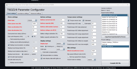
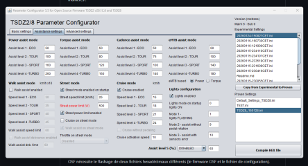
I’m reaching out because I’m a bit stuck.
I have a simple setup: TSDZ8 750W from Varstrom, EKD01 display, and a 14.4 Ah battery.
I’m having several issues:
When I flash a firmware (Katana 2 or Spyder 3), then configure it with Java Configurator and flash again, I end up with no assistance at all, no matter which level (1 to 5).
I restored the original firmware I had backed up before flashing, and everything works normally again (motor and throttle).
I’ve ridden about 85 km since restoring the original firmware, and this morning I had another issue:
the motor and battery power on normally, but as soon as I apply torque and the motor starts, everything shuts off, including the display.
I have to turn the system back on each time.
If I stay on assistance 0, it does not shut off.
Last question: on the EKD01, how do you switch from street mode to cruise mode?
Thanks for your help.
About your issue with OSF, I suspect that you do not flash the controller in the expected way. You have to flash 2 different files (the firmware and the configuration). When you flash a file using the menu item (production programming) mentioned in the ebikestuff manual, by default it erases totally the chip before uploading a file. So when you flash your second file, it erases all and so also the first file you already flashed. You have to select another menu (named "manual programming") in jorder to avoid this erase.Hello everyone,
I’m reaching out because I’m a bit stuck.
I have a simple setup: TSDZ8 750W from Varstrom, EKD01 display, and a 14.4 Ah battery.
I’m having several issues:
When I flash a firmware (Katana 2 or Spyder 3), then configure it with Java Configurator and flash again, I end up with no assistance at all, no matter which level (1 to 5).
I restored the original firmware I had backed up before flashing, and everything works normally again (motor and throttle).
I’ve ridden about 85 km since restoring the original firmware, and this morning I had another issue:
the motor and battery power on normally, but as soon as I apply torque and the motor starts, everything shuts off, including the display.
I have to turn the system back on each time.
If I stay on assistance 0, it does not shut off.
Last question: on the EKD01, how do you switch from street mode to cruise mode?
Thanks for your help.
About your issue with the original firmware, I suspect that you have a cell of your battery that is defect. Your battery has probably a BMS (battery management system) that controls the voltage of each of the 13 (for a 48V battery) groups of n cells. If one cell is defect, the voltage of one group could drop below a minimum level (e.g. 2.8V) and then the BMS act like a fuse and does not allow any current. As the defect concerns only one group, the total voltage of the battery could still be high (e.g. a 48V battery could have a total voltage of 12*4.1V+1*3V= 52,2V with one defect cell). I suggest that you try another battery if possible.
Mstrens,
Thank you very much for the reply. I checked with two different 48V batteries: a 14.4Ah and an 18Ah, both showing a voltage of 54.2V. I’m more inclined to suspect the motor side.
I had flashed both .hex files using the manual programming method. I will try reflashing both files again using manual programming.
I’ll keep you updated over the next few days on the progress.
Thank you.
Thank you very much for the reply. I checked with two different 48V batteries: a 14.4Ah and an 18Ah, both showing a voltage of 54.2V. I’m more inclined to suspect the motor side.
I had flashed both .hex files using the manual programming method. I will try reflashing both files again using manual programming.
I’ll keep you updated over the next few days on the progress.
Thank you.
Hi all,
It's been a while since I followed the topic of osf for the tsdz8.
Thanks to mstrens and the many testers here, a lot has happened in the meantime. I'm currently building another bike with the motor and wanted to ask what the current status of osf is
- Is the original FW still more efficient?
- Does the osf still feel “weak” compared to the original firmware?
- Can I use the latest version with the EKD01?
In any case, thank you for all the great work!
It's been a while since I followed the topic of osf for the tsdz8.
Thanks to mstrens and the many testers here, a lot has happened in the meantime. I'm currently building another bike with the motor and wanted to ask what the current status of osf is
- Is the original FW still more efficient?
- Does the osf still feel “weak” compared to the original firmware?
- Can I use the latest version with the EKD01?
In any case, thank you for all the great work!
You can try the file OSF_TSDZ8_VLCD5_SPIDER_3_V00_02.01.hex in branch test6_with_pll.Hi all,
It's been a while since I followed the topic of osf for the tsdz8.
Thanks to mstrens and the many testers here, a lot has happened in the meantime. I'm currently building another bike with the motor and wanted to ask what the current status of osf is
- Is the original FW still more efficient?
- Does the osf still feel “weak” compared to the original firmware?
- Can I use the latest version with the EKD01?
In any case, thank you for all the great work!
It is at this link : GitHub - mstrens/OSF at test6_with_pll
This is the latest version I made. It is supposed to be more efficient than previous version because best lead angle is automatically calculated based on some parameters. It is still in a test branch because I got only 2 feedbacks (probably for the 860C display version) and I am not sure the parameters are already the best one.
In this version, I did not yet tried to increase the max current compare to previous versions.
You can look at some previous posts in this forum to know more about the changes I made.
Does this version work with 860C also? I have the 860C with installed version OSF_860C test6_with_pll. And the motor is getting overcurrent warnings quite often. Even without particularly heavy load some times. I've tried increasing "overcurrent delay" as suggested and also setting it to 0. But no difference. Otherwise I think the version is an improvement. Thanks mstrens!In version 0.2.xx, I also measure each of the 3 currents between each low side mosfet and ground and I check that they do not exceed some values.
Here is a version (for vlcd5 (and similar) display where I disabled those checks.
The original check from 0.1.XX version based on the total current is kept but can be disabled setting
overcurrent_delay on 0.
Use it at you own risk.
There is a different version for 860C display (having the same changes). It is here : OSF_860C/files_to_flash at test6_with_pll · mstrens/OSF_860CDoes this version work with 860C also? I have the 860C with installed version OSF_860C test6_with_pll. And the motor is getting overcurrent warnings quite often. Even without particularly heavy load some times. I've tried increasing "overcurrent delay" as suggested and also setting it to 0. But no difference. Otherwise I think the version is an improvement. Thanks mstrens!
Still someone noticed also the overcurrent warnings. This has been discussed in some previous posts ( see here above). In post 1234 you can find a version (not available on github) where I disabled some more checks that I added. If this solve the issue, I could put a version on github where I enable the checks but increase the levels.
Yes TSDZ2's 860C display works fine on TSDZ8.I have today TSDZ2 with 860C display, if I upgrade to TSDZ8 and I still use the same display ?
Thank you, is it the prefer display also when you are using OSF firmware?Yes TSDZ2's 860C display works fine on TSDZ8.
You are wellcome. I use OSF and 860C works fine. If you want use original OSF then you need 860 C display with different connector.Thank you, is it the prefer display also when you are using OSF firmware?
Here is @mstrens OSF for 860C display:
GitHub - mstrens/OSF_860C
Contribute to mstrens/OSF_860C development by creating an account on GitHub.
 github.com
Not sure if this is helpful, but I decided to share my feedback about using test6_with_pll. I've been using it for a few weeks now. In general, it works well — assistance maybe feels smoother than before (main branch).
I saw overcurrent mentioned here, and I experienced it twice as well. What’s interesting is that these were not situations where I would normally expect overcurrent to happen. For example, once it stopped with an overcurrent error on a snowy hill. Because of going slowly on an "easy" gear, the slippery surface and spinning wheel, I wouldn’t expect current to peak.
While writing this, I had a thought about why it could happen. On an icy surface, the wheel could slip for a moment, making it impossible for my legs to follow the pedals fast enough. That could create an instant load increase on the motor, which might reasonably trigger overcurrent. One moment the motor spins easily because it’s slipping on ice with leg assistance, and the next moment it suddenly catches traction while my legs are not helping because they couldn’t keep up with the rapid slipping.
One more thing I wanted to ask about.
Yesterday I installed brakes with a braking sensor. It works very well, but I’m interested in what the braking signal actually means for the motor. Initially, I thought it just cuts current to zero, but now I’m not sure, because:
When I use the throttle to spin the wheel while not moving, and at the same time apply the brake, I can hear a click in the motor. At the same time, I see the front sprocket stop almost instantly, like something is actively braking it from inside the motor.
When I ride the bicycle with constant pressure on the pedals and press the brake lever just enough to send a signal to the motor (without actually braking the wheel), I can feel that click through the pedals. At that time, nothing visibly stops spinning because I’m still pedaling.
I would expect the braking sensor to behave like releasing the throttle — the motor would just quietly stop spinning. But since it behaves differently with the brake sensor, I’m really interested in what is happening inside, and whether using the brake during motor peak current or peak speed could harm the motor.
If someone has an easy explanation, I’d be happy to hear it
I saw overcurrent mentioned here, and I experienced it twice as well. What’s interesting is that these were not situations where I would normally expect overcurrent to happen. For example, once it stopped with an overcurrent error on a snowy hill. Because of going slowly on an "easy" gear, the slippery surface and spinning wheel, I wouldn’t expect current to peak.
While writing this, I had a thought about why it could happen. On an icy surface, the wheel could slip for a moment, making it impossible for my legs to follow the pedals fast enough. That could create an instant load increase on the motor, which might reasonably trigger overcurrent. One moment the motor spins easily because it’s slipping on ice with leg assistance, and the next moment it suddenly catches traction while my legs are not helping because they couldn’t keep up with the rapid slipping.
One more thing I wanted to ask about.
Yesterday I installed brakes with a braking sensor. It works very well, but I’m interested in what the braking signal actually means for the motor. Initially, I thought it just cuts current to zero, but now I’m not sure, because:
When I use the throttle to spin the wheel while not moving, and at the same time apply the brake, I can hear a click in the motor. At the same time, I see the front sprocket stop almost instantly, like something is actively braking it from inside the motor.
When I ride the bicycle with constant pressure on the pedals and press the brake lever just enough to send a signal to the motor (without actually braking the wheel), I can feel that click through the pedals. At that time, nothing visibly stops spinning because I’m still pedaling.
I would expect the braking sensor to behave like releasing the throttle — the motor would just quietly stop spinning. But since it behaves differently with the brake sensor, I’m really interested in what is happening inside, and whether using the brake during motor peak current or peak speed could harm the motor.
If someone has an easy explanation, I’d be happy to hear it
Similar threads

- Replies
- 44
- Views
- 1,425
- Replies
- 16
- Views
- 3,734

- Replies
- 4
- Views
- 3,789
- Replies
- 5
- Views
- 7,206

- Replies
- 102
- Views
- 14,985