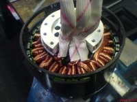
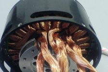
Turnigy CA120-70 8600W Brushless Outrunner (100c eq)

olaf-lampe said:
@Biff
I conclude that a low voltage/high current application would be best then? Rewind the beast with a low turn count and thicker strands and pump some 300-400Amps through it. :twisted:

-Olaf

The way it is wound right now would be good for a low voltage (30V, 300A) which would give around 4,000 RPM. Rewind it with 2x the turns would get you the same output power (speed and torque) at 60V, 150Amps and be easier to control. These are still just initial estimates, without real testing or proper simulation the heat production and heat extraction is hard to estimate so I could be way off.
 
Biff said:
The way it is wound right now would be good for a low voltage (30V, 300A) which would give around 4,000 RPM. Rewind it with 2x the turns would get you the same output power (speed and torque) at 60V, 150Amps and be easier to control. These are still just initial estimates, without real testing or proper simulation the heat production and heat extraction is hard to estimate so I could be way off.
Or try to rewire it to wye?
Actually I have a sevcon millipaq controller, which has worked best for my brushless Etek ( ~40V/400A max.). Max. rpm with the Etek was 4000rpm. Don't know how many poles it has?
Probably an issue with the high polecount of the CA120?

I'm afraid, when I rewind it, it would still have a very low resistance, due to the higher copperfill...
I need some irfb3006 FETs, they seem to suit best. (In combination with a centrifugal clutch to keep startup currents low)
-Olaf
 
olaf-lampe said:
I'm afraid, when I rewind it, it would still have a very low resistance, due to the higher copperfill...
I need some irfb3006 FETs, they seem to suit best. (In combination with a centrifugal clutch to keep startup currents low)
-Olaf

The resistance is easily calculable/predictable. You can easily increase the resistance to basically anything you want (With the exception it's a discrete instead of continuous distribution, assuming the same copper fill).
 
swbluto said:
olaf-lampe said:
I'm afraid, when I rewind it, it would still have a very low resistance, due to the higher copperfill...
I need some irfb3006 FETs, they seem to suit best. (In combination with a centrifugal clutch to keep startup currents low)
-Olaf

The resistance is easily calculable/predictable. You can easily increase the resistance to basically anything you want (With the exception it's a discrete instead of continuous distribution, assuming the same copper fill).

If I'd follow biffs conclusion, I would wind with 2x turncount as it is now. I don't know, how I can easily increasy the resistance to anything I want in that case?

-Olaf
 
Mine arrived. You could get another wrap on these teeth if you wanted to take the time. It would increase resistance and inductance by a little bit, and reduce copper losses and improve efficiency a bit.
 
HumboldtRc said:
Will someone please test it without the skirt-bearing.

I'm going to use a flange-mount bearing rated for 2800lbs, in my project, so i wont be needing the skirt-bearing.

I don't need a skirt bearing for my appliction either. As soon as I get a free hour, I will pull the motor apart, remove the skirt section, and get some no-load figures. I don't have a way to measure inductance this low with any accuracy, so I'm going to try to use a precision LCR meter from UW or some other local college and get the inductance quantified finally.
 
olaf-lampe said:
swbluto said:
olaf-lampe said:
I'm afraid, when I rewind it, it would still have a very low resistance, due to the higher copperfill...
I need some irfb3006 FETs, they seem to suit best. (In combination with a centrifugal clutch to keep startup currents low)
-Olaf

The resistance is easily calculable/predictable. You can easily increase the resistance to basically anything you want (With the exception it's a discrete instead of continuous distribution, assuming the same copper fill).

If I'd follow biffs conclusion, I would wind with 2x turncount as it is now. I don't know, how I can easily increasy the resistance to anything I want in that case?

-Olaf

If you're limiting yourself to a 2x turn count, you could always reduce the copper fill (Use thinner wire and/or less parallel wires). :mrgreen:

I don't know why you're limiting yourself to 2x, though. If you triple the turn count, you increase the resistance by a factor of 9. Quadruple it, a factor of 16. You get into pretty high resistances fairly quickly.
 
Removed the skirt bearing and tested it again:
13.8V => 7.x A
44V => 17.x A
not much better, it really seems to be iron loss.

BTW, disassembly was a pleasure. Everything falls apart like butter. Also wye-rewiring is easy.
-Olaf

I also added a soundfile, the microfone had a hard time to record this supersonic noise... :D

ca120_noskirt.jpg

ca120_wye.jpg
 
[youtube]lBPknG7oG6U[/youtube]

BEMF waveform is sinus.
 
I recall Recumpence mentioned fitting sprockets to these might be a problem as Matt mentioned it is with the Plettenberg Predator rc motors which also lack a shaft, i remembered the cart engine sprockets, these could easily be adapted to bolt on couldnt they?

http://kart-master.com/Rotax_Leopard_Sprockets.html

Get to use the #219 chains alot rave about too :)

KiM
 
Exactly Kim. Flange mount sprockets are the hot ticket for this motor. That whole protruding prop mount stub unbolts, and a flange mount 219 or silent chain sprocket can bolt right up there making a narrow compact simple package.
 
I just found out .. My motor is ca120-80 with longer magnets and Can... So dont take my data to considering .. since its actually different motor... as factory says.. Can you confirm the lenght of magnets in ca120-70 ?
 
I rewired the stator in wye and installed the skirt bearing again. Without the skirt bearing the bell wasn't running very well. The shaft bearings are from thailand.
I expect a kV of 150/1.7= 88.
Ri should be 15mOhm.
The new no load currents are:

13.8V => 4.4A
46V => 8.2A @ 4000rpm

I try to install halls next time and use an infineon with 60V. Lets see where the sweet spot of the motor will be.
I also have a turnigy aquastar 240A controller coming my way. It'll have no problems with the motor in wye, I guess. (I will use a centrifugal clutch for the pocket bike too)

-Olaf
 
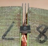
Mounting halls in the slots is no option. The gap between the stator teeth is 2mm while the halls are 4mm wide :(hall closeup.jpg
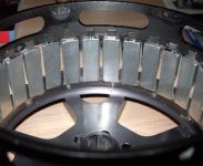
But we have 14mm between the stator heads and the skirt bearing. So I decided to add 28 small magnets in the bell and mount the halls to an internal bracket. To avoid distortion between the phase cables and the hall outputs, I'll drill an separate hole in the stator foot for the hall cables.
added hall magnets.jpg
Since the motor has 28 magnets, the angle between each sensor should be 8.57°.
120°/14=8.57°
Given an inner diameter of 110mm from magnet to magnet and an airgap for the halls of 0.5mm I calculated the distance between the sensors to become 8.12mm.
109/2 x sin(8.57)=8.12
Is that correct so far?

-Olaf
 
http://www.ondrives.com/gearboxes-reducers-inline-low-backlash-taper-gearbox-8mm-input-12mm-output.html
not so much cost effective, but what do you think about this gearbox for that motor ?
 
or this : http://www.qtcgears.com/e-store/RFQ/default.asp?Page=Pg_5-002.html
all right , i will stop now :)
 
Miles said:
Marko,

You need to multiply the motor torque by the gear ratio and compare that figure with the output torque rating of the gearbox.

Or,

you know how much torque the tire can stand before it starts to slip. That's roughly the max. torque you'll see in your system. ( beside some torque ripples ).
With that numbers you can calculate backwards to search for the right gearbox. Better choose a gearbox that can stand twice the torque.

-Olaf
 
olaf-lampe said:
Miles said:
Marko,

You need to multiply the motor torque by the gear ratio and compare that figure with the output torque rating of the gearbox.

Or,

you know how much torque the tire can stand before it starts to slip. That's roughly the max. torque you'll see in your system. ( beside some torque ripples ).
With that numbers you can calculate backwards to search for the right gearbox. Better choose a gearbox that can stand twice the torque.

-Olaf
I have a feeling the front end will be off the ground before the tire slips. :mrgreen:
 
How much do you guys think the aluminum can, will effect the performance?

Is the stock aluminum can version going to be pulling th same amps, as a steel can modified one? Or does the aluminum make it pull less amps? And how is the translated to actual work?

Which would be more efficient? or would they be the same because one pulls less amps and therefore puts out less power......

And anyone with plans to make a steel one?

Also can you please tell me the length and width of the magnets.. And diameter and length of the stator and length of tooth on the stator... Thanks ( i want to compare the dimensions to the ones i have in hand, as the are always different for the stated numbers)
 
HumboldtRc said:
How much do you guys think the aluminum can, will effect the performance?

Is the stock aluminum can version going to be pulling th same amps, as a steel can modified one? Or does the aluminum make it pull less amps? And how is the translated to actual work?

Which would be more efficient? or would they be the same because one pulls less amps and therefore puts out less power......

And anyone with plans to make a steel one?

Also can you please tell me the length and width of the magnets.. And diameter and length of the stator and length of tooth on the stator... Thanks ( i want to compare the dimensions to the ones i have in hand, as the are always different for the stated numbers)

I believe it's been confirmed as steel.
 
Back
Top