two switches, one actuator (circuit diagram help needed)

jimmyhackers

10 kW
Joined
May 11, 2015
Messages
609
hello all.

been scratching my head and ive come up flumped for a simple circuit....need some help

essentiall i need two spst switchs as inputs to controll an actuator, to power and reverse its polarity. so it can go back and forth.
the switches are alarm floor pressure switches that have been modified (shrunk) to fit some boots.

all my ideas so far have envolved 2 relays and work but when both switches are pressed together (a possibility in the things application) im pretty sure ill end up shorting out the battery :s

so if someone could draw me a circuit diagram and post it, id be most gratefull

thanks in advance
jim
 
Continuous Cycle?

1 relay and two mom. Switches ok?
1 mom. NC and 1 mom. NO is easiest.
 
Here are a couple ways. Manual operation while holding F or R button.
Auto cycle with limit switches to change direction.

revactu.png

I can draw one up when I know what you need.
Dynamic braking?
 
thanks for the replies. your help is greatly appreciated

um...check my other post about an exo suit : D

ive ammassed rather a few linear actuators. of variouos sizes, operation and states/sizes of controll boxes...
this makes controlling something im walking in rather mentally and physically taxing to all be done by hand pressing buttons.

i have to use two flexible "normally open" spst switches as pressure pads per actuator mounted in the boots ect. so i can i have a "semi-passive" controll of the machine"
essentially i cant use anything but spst as the inputs.

also adapting all said controll boxes per actuator means a rather big box to store it all in and probaly even more of a birds nest of cables.

i need something small, cheap and with 8 terminals. 2 for battery, 2 for motor and 2 per switch. that can handle 24v and about 3amps. also id like it to do "nothing" if both switches are pressed together.

heres a naff/primaive drawing of what i want. i just need the "yellow" controll box


thanks for your help again
 
i think its the top circuit you drew i want....dont spose you could help me find a small cheap verison of it on ebay or somewhere else?
 
So, when press one switch = moves in only while pressed.
Other switch = moves out only while pressed.
Both switches = no effect.
 
If yes. Top one works. Bosch relays are cheap and robust.
Don't think you need the surge suppression shown above motor.
Only two relays and two switches.
This circuit brakes dynamically.
If you want solid state or only one relay, I will design something.
If you would like PWM/soft start, use a reversing scooter controller.
I use scooter controls on some industrial machines.

 
thanks so much for the help

i think i have found what i need (i figure its a more complicated version of the diagram you posted)

http://www.ebay.co.uk/itm/112181576344?_trksid=p2060353.m1438.l2649&ssPageName=STRK%3AMEBIDX%3AIT

this comes with the added bonus of a speed control potentiometer, but tbh this function wont be used as the actuators are slow enough as it is :)
i cant find anything smaller or cheaper so think these will do for initial testing

this unit is 57x37x21mm..... and most definately cheap enough. the size is "bearable". i should be able to fit around 5-6 of these in my current controller box along with a small lipo.
so far ive only got a few actuators so space for six atm is plenty enough.

however, i doubt this will be the last exo suit i buiild as all my (high in the sky) plans have envolved 18 servos.

if you think you can make/design a smaller unit maybe using transistors....id still be very interested. (also 3amps is a bit wimpy, maybe 5 or even 10amps could be desirable if it doesnt effect size to drastically)

thanks again
 
hey again.....the above items arrived.

their designed functionality was great.....however their actual functionality was less than desirable.

essentially, every now n then the items i ordered have sticky relays.

so yes please please please can you design me a "solid state" transistor-type version so i can negate this problem.

failing that can you point me in the direction of a "solid state" relay replacement that i can swap these mechanical relays out for please

thanks again
jim
 
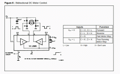
What you need is an H-bridge circuit. I'll see if I can find a simple one that can be controlled with switches.
How much current?
 
This looks like it.
http://www.ebay.com/itm/Dual-H-Bridge-Stepper-Motor-Drive-Controller-Board-Module-For-Arduino-L298N-OS-/162317342929?hash=item25cade18d1:g:F2YAAOSwHjNV-~sh
Is $1.79 in your budget?
Can't understand the Chinese instructions yet. I'll study it.

Complete chip pdf if it has to be hacked. https://www.sparkfun.com/datasheets/Robotics/L298_H_Bridge.pdf
 
Maybe the Ebay listing is clear to someone else. I'm a little slow this morning.
At first look:
3 pin terminals are motor power in and 5V out.
2 sets of out put terminals to 2 dc motors. Reversible thru dual H-bridge chip. Diodes one-board.
Set of jumpers for coast stop or dynamic braking.
Header controls both motor on-off and directions independently.
Pull up/down on logic pins may be required.

Data sheet shows parallel connection for 4 amps.
 
the actuators are running at 24v dc and roughly 2-3amps current... the wattage one one says 60w.

hm.... the functionality with that chip seems possible but im not quite sure due to the chinglish...
i have a feeling its not quite what i want. which is shame because by all accounts itll will run two motors per board.... im just failing to see where i could "connect" four independant spst switches to it....unless its the jumper parts.

http://www.ebay.com/itm/181883209475?_trksid=p2060353.m1438.l2649&ssPageName=STRK%3AMEBIDX%3AIT

i found these as a SPDT solid state relay..... but at over 6 quid a pop and needing 2 per board im reluctant... i wondered if i just swapped out the current board mounted relays with some better quality ones it might fix them.
 
jimmyhackers said:
the actuators are running at 24v dc and roughly 2-3amps current... the wattage one one says 60w.

hm.... the functionality with that chip seems possible but im not quite sure due to the chinglish...
i have a feeling its not quite what i want. which is shame because by all accounts itll will run two motors per board.... im just failing to see where i could "connect" four independant spst switches to it....unless its the jumper parts.

http://www.ebay.com/itm/181883209475?_trksid=p2060353.m1438.l2649&ssPageName=STRK%3AMEBIDX%3AIT

i found these as a SPDT solid state relay..... but at over 6 quid a pop and needing 2 per board im reluctant... i wondered if i just swapped out the current board mounted relays with some better quality ones it might fix them.


They are ac relays.
Probably triac output.
I could get one to see how to connect if you have trouble.
Are you talking about the chip or the pcb circuit on ebay?
The pcb is ready to go.
 
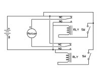
Here's about the simplest way to do it. You need two small relays that can handle the current.

The momentary switches activate the relay coils. When both switches are off (or both on), the motor is shorted, which will make the actuator motor stop very quickly. No condition will cause the battery to be shorted.


Actuator schematic.jpg
 
That's the one he rejected in post three. Showing common bosch relay numbers.
I like relays too. :D
 
Inwo said:
That's the one he rejected in post three. Showing common bosch relay numbers.
I like relays too. :D

Doh!
I should open the attachments.

Making a solid state version with an H bridge will work but may require a PC board.
Here's a couple that look like they would work:

From Mouser- http://www.mouser.com/ProductDetail...=sGAEpiMZZMtKB4wrjsn3leBIKZjt0HKaMBkNcqyw2ec=

Another one with a smaller package:
http://www.mouser.com/ProductDetail...GAEpiMZZMtKB4wrjsn3ld//FzKjZ%2bdbqmc3S1gWDEY=

Check the datasheets. It looks like it should do what you want. Some heat sink may be a good idea.

BTW: There is a guy at UC Berkeley working on various types of exosuit. One is for paralysis patients to get physical therapy and gradually restore movement. Other designs for augmenting muscles to prevent repetitive stress injuries or just fatigue. I like the big one in the movie Alien.
 
Sorry to keep adding to the confusion.
The link I gave to Ebay was the complete pcb solution to driving and reversing two motors from logic inputs. (I think) China speak description.
At most it will need pull up resistors, as it has onboard 5v supply.
See if you can help decipher and recommend for a solution.

http://www.ebay.com/itm/Dual-H-Bridge-Stepper-Motor-Drive-Controller-Board-Module-For-Arduino-L298N-OS-/162317342929?hash=item25cade18d1:g:F2YAAOSwHjNV-~sh

It looks like two enable pins and 4 direction pins.
Hopefully enable can stay jumped and control thru direction pins.
 
for 1.98 each i may as well have go and try the h bridge device.

i didnt reject the previous relay device.....i may still end up using it. its just for the price of the things i got.... it was cheaper than what my time would of been to make them, but then their realys started sticking.....so im kinda glad i preempivly asked for a solid state version ,although it was due to smaller form factor requirements and not reliability of mechanical relays (not sticking).

as i say ill try one of those hbridges and see if they do the job.
i said i didnt quite understand the adverts wording....will i need a seperate 5v power supply for this? or it it saying this has a seperate 5v power output supply (like a BEC of an ESC)?

thanks again for all your help guys

and mines more like a small power loader suit from aliens :D
 
It has the 5 volt supply onboard.
I don't understand China speak either, but it should work.
If all else fails I'll get one to test.
 
theyve finally come.

work like a charm.....and i can power two actuators off of one board. double the space saving :)

thanks again for all your helpl

jim
 
Back
Top