fechter said:
I'm not exactly following what the circuit is doing. Are all the coils on the same core?
There are some off-the-shelf chips that can do non-dissipative balancing using discrete inductors. Check out this one from TI:
The EMB1499Q bidirectional current dc/dc controller IC works in conjunction with the EMB1428 switch matrix gate driver IC to support TI’s switch matrix based active cell balancing scheme for a battery management system. The EMB1499Q provides three PWM MOSFET gate signals to a bidirectional forward converter so that its output current, either positive or negative, is regulated around a user-defined magnitude. This inductor current is channeled by the EMB1428 through the switch matrix to the cell that needs to be charged or discharged. In a typical scheme, the EMB1499Q-based forward converter exchanges energy between a single cell and the battery stack to which it belongs, with a maximum stack voltage of up to 60 V. The switching frequency is fixed at 250 kHz. The EMB1499Q senses cell voltage, inductor current and stack current and provides protection from abnormal conditions during balancing.
http://www.ti.com/product/emb1499q
If you look at the datasheet, you can see how they do it.
Another approach is to drive a small transformer across each cell and have all the transformer outputs feed the main pack terminals (through diodes). Transformer drive is turned on only for the high cells until the low cells catch up. This way you can use off-the-shelf transformers that are relatively cheap. Ones used for PoE applications are very common and have a good turns ratio for this. You could easily get 3A of balance current without generating much heat.
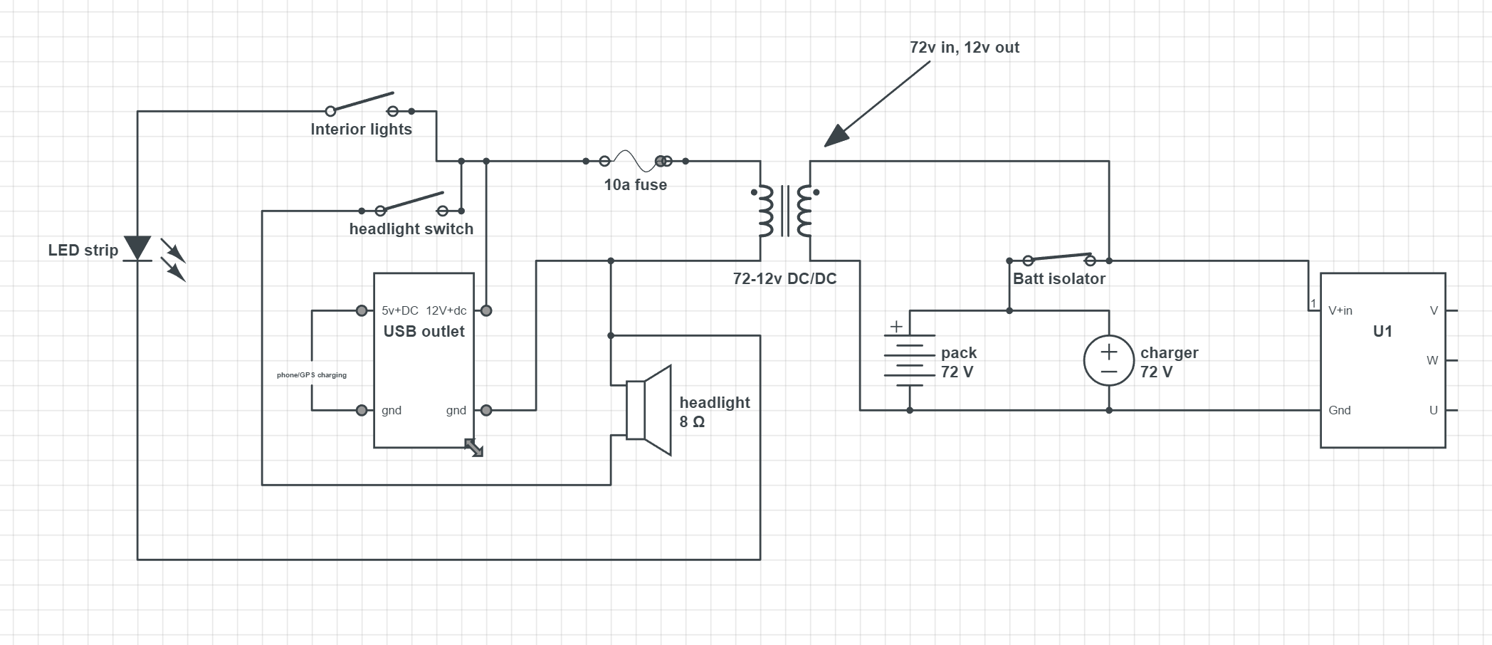
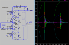
Yes, all on same core. One wind more than cell count.
That behavior by the directive K1 L1 L2 L3 L4 L5 0.99
-----
I work for TI, indirectly. Just down the street. We build
the EVM circuit boards (including various BMS and motor
controllers). I test them. Havn't seen EMB1449. Might be
another of TI's contract manufacturers had the privilege
to built that project.
OK, $399 to buy from TI store, not going on my bike...
http://www.ti.com/tool/em1402evm
As for get the chip and DIY it, Its three chips including
the microcontroller, 24 FETs to switch the cells. 4 fets
to switch the converter. Needs floating 12V bias supply,
also 5V and 3.3V. Would have to compile firmware in
code composer, which sounds way too much like work
to be fun. I'm a test tech, not a programmer anyway...
So, my circuit is intended to be dumb and open loop.
Of bare minimum component count, and dirt cheap.
My bill counts what? One FET per cell, plus Schottky.
Transformer might be a pain, but all winds are near
the same small voltage, could wind together as one
twisted bundle. Might be suitable cores and bobbins
that clip together, or JBWeld some hi-flux blocks.
If pulsed by MSP430 or ATTiny, only blink the LED
code that needs modified, maybe I can handle that.
Slightly more comfortable with an analog 555.
Power from middle two cells, AC couple requires
no float. Yeah, I'm going analog...
As for the UVLO, we did build that isolator's EVM.
I've already played with it enough to be sure that
part is going to work. Even tho the spec doesn't
confirm proper operation below 3V VCC1, passed
steady ON signal all the way down to 2.5V UVLO.
Might worry of low voltage abuse if I were trying
to pass a more interesting signal.
-----
Not shown in drawing, but also not forgotten:
Fusible links per cell and 4.15V shunt regulators.
Shunt build in progress. Veroboard dead-bug
mess, cause I'm not a layout guy either. Whole
assembly not quite finshed, but first cell works.
Each shunt is a TIP106G PNP darlington with
built-in bias resistors and 3 external ohms in
series with the collector. Driven by a TLV431
1.24V shunt regulator. Fed by resistor totem
2.32K above 1K. Scaling to about 4.15V~4.19V
depending temperature. Will draw if needed.

")