Use Xtyle Controller for Schwinn AL1020

The7

10 kW
Joined
Jul 11, 2007
Messages
761
Location
Vancouver
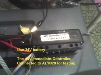
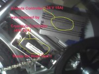
My Schwinn AL1020 uses Ananda 24V 15A controller.
Have already tried it on 36V supply with good results.
See: http://endless-sphere.com/forums/viewtopic.php?t=1636

Would like to work the motor from 48V battery.

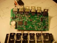
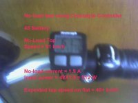
Bought an used Xtyle 48V controller this afternoon. This used controller was tested OK at no-load feeding an 404 motor with 36V and 54V in the shop.
Anyone regonize this Xtyle controller?


Took home and did some bench test without connecting to my motor unit.
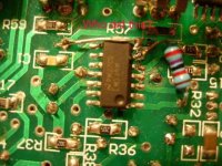
Hall sensor supply was measured to be 13.6V.

1)Could the stock Hall senors stand the 13.6V? Don't want to damage the sensors in the motor.

2) If using 5V from throttle supply, could the 5V Hall signal work OK on Xtyle?

Forgot to ask what is the "?" socket for.

Need to do a bit more research and measurement.
 

Attachments

  • DSCN7248 copy.jpg
    DSCN7248 copy.jpg
    48.1 KB · Views: 5,403
This controller has:

NEC C1246 commutator:
three IR2101 gate drivers;
six IRF3205 FET.

But unable to find the PWM chip.
 

Attachments

  • DSCN7253 copy.jpg
    DSCN7253 copy.jpg
    33.2 KB · Views: 5,395
  • DSCN7254 copy.jpg
    DSCN7254 copy.jpg
    38.3 KB · Views: 5,392
  • DSCN7255 copy.jpg
    DSCN7255 copy.jpg
    39.5 KB · Views: 5,390
  • DSCN7256 copy.jpg
    DSCN7256 copy.jpg
    19 KB · Views: 5,387
In AL1020 motor, the Hall sensor output is 0 V and 5V if the Hall sensor suppy is 5V.

Need help to know:

1) What is the typical Hall sensor output for the Crystalyte 4XX Motor if the Hall supply is 13V?

2) If the Hall sensor output is 0 and 5V, wiil the Crystalye Controller work?
 
"The following have to be sorted first:

1) The Hall sensor signal and supply of my stock controler is 5V.
But it seems that Xtyle use 6.8 V for the Hall signal as per Fretcher!
It seems a bit odd because most logics use 5V signal.
Could the stock Hall sensor stand 6.8 V?
If 5 V is used for Hall suppy, will the 5V Hall signal work for Xtyle?

2) The phase-sequence of the stock is Y-B-G.
Xtyle also use the same color code; Y, B and G.
But what is the phase-sequence of Xtlye?

3) Output Vyb leads Hall signal Hy by 60 deg.
What is their phase relationship in Xtyle?"

I raised the above questions in anther post and after further bench test on the switching relationship between the Hall sensor signals.

In order to get the same phase relationship between the Voutput and Hall signals for Xtyle controller when using in my AL1020 ebike.

Motor winding - Xtyle Output
Yellow - Yellow
Blue - Green
Green - Blue

Motor Hall sensor output - Xtyle Hall signal input
Yellow - Yellow
Blue - Green
Green - Blue.

If you match the color of the motor to Xtyle controller, the Voutput will be retarded by 60 deg which is not right for the motor.
I don't know the exact outcomes and I think that the motor still could turn but with an reducing torque (?) and increasing battery current (?).
Would like to test this later if possible.
( LATER TESTING shows - There is NO rotating torque and the battery current is very high (limited by controller). Evenutally the battery is completely cut-off by the protective circuit)


The above is not yet tested with motor because of the Hall voltage matching (5V vs 13.6V).

Still doing some research on this.
 
The7 said:
"

I raised the above questions in anther post and after further bench test on the switching relationship between the Hall sensor signals.

In order to get the same phase relationship between the Voutput and Hall signals for Xtyle controller when using in my AL1020 ebike.

Motor winding - Xtyle Output
Yellow - Yellow
Blue - Green
Green - Blue

Motor Hall sensor output - Xtyle Hall signal input
Yellow - Yellow
Blue - Green
Green - Blue.

The Xtlyle controller was tested using pseudo Hall signals and the above connection should be used to match AL1020 motor.

Also the postion of the color 3-phase wires are shown to be different. Look at the position of blue and green phase wires.
 

Attachments

  • DSCN7166 c.jpg
    DSCN7166 c.jpg
    48 KB · Views: 5,298
  • DSCN7248 copy.jpg
    DSCN7248 copy.jpg
    48.1 KB · Views: 5,297
Some test Xtyle controller using pseudo Hall signals.

Phase-sequence = y-g-b
Pseudo Hall signal = 13 V
Output Voltage = approx 24V p-p.

For pure resistance load, the waveform is in steps up/down.
Each step should be 60 deg.

If a motor were connected, the steps will become slopes due to the back emf and the inductance of the motor.
 

Attachments

  • 04-08-07_1720 b.jpg
    04-08-07_1720 b.jpg
    36.9 KB · Views: 5,295
  • 04-08-07_1720 copy.jpg
    04-08-07_1720 copy.jpg
    31.6 KB · Views: 5,293
Initial test Xtyle on AL1020;

The Xtyle was connected to AL1020 according to the correct phase sequence (and no match for color)

An 7805 was used to drop the "13V" to 5V for the motor Hall sensor supply.

1) The motor started right the frist time and took similar battery current as the stock controller. There is no need to fiddle around the color combination if you know the phase-seq of the controller.

2) From the output waveform, Xtyle does the PWM on the high-sided FETs.

3) Using the rear brake to load, the controller limited the current to 18A.
Road test will be conduct later to find whether this higher current limit would give a higher torque

4) The controller will cut off the supply to motor if the throttle in ON and the wheel is not rotating for 1 or 2 sec. To return the throttle to OFF will reset the cut-off.

5) The 48V old version controller works at 24V. It seems there is no LVC??

6) No-load top speed at 24V is same as the stock controller.

7) To be no-load test on 36V and 48V later to find the no-load max speed.

8) The "13V Hall supply" was only the o/c voltage. It drops to 5.9V when load. The 7805 is not needed and will be removed and connected directly later.
 

Attachments

  • 05-08-07_0000 copy.jpg
    05-08-07_0000 copy.jpg
    30.2 KB · Views: 5,265
Interesting.

The 7805 supplies power for the throttle.

Correct, the PWM is on the high side FETs. I think this is done because the high side uses a bootstrap circuit to supply the gate voltage (10v above the battery voltage).

So, with the pseudo-hall inputs, does that mean the motor halls are not needed?
 
fechter said:
Interesting.

The 7805 supplies power for the throttle.
The 7805 is not for the throttle.


The 7805 was supposed to drop the Hall suppy from X-controller for the Hall sensors of the motor.
The Hall suppy of the X-controller is 13.6V when not loaded. When it is fed into the Hall sensors, it would drop to 6-8 V with a load current of about 10 mA. So the 7805 was removed and an simple led is used to drop it from 7 to about 5 for the Hall sensors. It works with no problem.

fechter said:
Correct, the PWM is on the high side FETs. I think this is done because the high side uses a bootstrap circuit to supply the gate voltage (10v above the battery voltage).
Yes, for the X-controller.
But for the stock Ananda Controller, the PWM is on the low-side FETS.
The frequency of the PWM for X-controller is 17kHz.
That of Ananda controller is 35KHz which is double.
I don't think that I could hear 17kHz in my age. But some young one could hear it.
The X-controller seems to exicte the motor to give an low audible noise which is not present in Ananda. I suspect that it is the sub-harmonics of the 17 kHz which could be 8.5Khz, 5.6kHz or 3.4 kHz.

fechter said:
Interesting.

So, with the pseudo-hall inputs, does that mean the motor halls are not needed?

The pseodo Hall signals are very close the orginal signal.
I am sure that it will work for an non-freewheeling motor.

Unfornately, I could not do this test because, my ebike has an free-wheeling hub motor. The motor could not be turned manually to give a staring back emf.
 
Bench Testing X-controller at 36V and 48V:

1) At 36V, the no-load top speed is about 45km/h (similar to Ananda Controller). Ananda gives a top speed at flat of 32-38km/h. X-controller would be about the same on flat and will do better on gentle slope due to a higher current limiting (19A vs 15A).


2) At 48V, the no-load speed is about 60 km/h. The expected speed on flat would be 40+ km/h.

a)No-load current at top-speed = 1.9A
No-load power input = 48X1.9= 91 watt

b) At full-throttle and used the rear brake to apply load until the battery current = 10A.
The speed droped to 44 km/h.
Power input = 48X10 = 480 watt.

c) Travelling at this loaded-speed, an 48V12Ah will be nearly EMPTY in 1 hour and the distance range will be 44 km.

d) 48V with 19A limit will give a peak input power of 900 watt.

3) Other comparisions with Ananda controller:

a) PWM of X = 17kHz ; X=Crystayle controller
PWM of A = 35kHz ; A= Ananda controller
Theorectically the PWM switching loss X is half of A.
Most ebikes have an top-speed frequency of 200Hz to 500Hz.
PWM of 17kHz should be higher enough for this top-speed.
However, 17 kHz PWM is in the audible range of young people which could be annoying.
As noted, a low level of sub-harmonic of the 17kHz was audible by me.
The 35kHz PWM is relative quieter.

b) PWM of X at high sided FETs.
PWM of A at low sided FETs.

c) Hall signal level of X = 13 V
Hall signal level of A = 5V
Signal of X is relatively noisy.

d) There is no problem of using the Hall supply of X on the Hall sensors of the motor.because the Hall supply when loaded is 6-8 V. An LED (dropping about 2V) will drop it to match the motor Hall sensors (about 5.5 V)

e) Phase sequence of X = y-g-b
Phase sequence of A = y-b-g

When phase-sequence was wrongly connected ( on X for testing purpose), the battery current reached 19A (limit) for 1-2 sec and cut-off and there was no sign of turning.
X has an inbuilt protection for non-rotating. It the throttle is turned ON and the motor is not rotating for any reason. The non-rotating protection will cut-off the supply after a short period 1-2 sec. In this short period, the controller may be hot enough to activate the thermal protection.
The motor will remain cut-off if you continue to hold the throttle ON.
It is reset automatically if you turn the throttle OFF.
Don't think that A has such non-rotation protection.

f) The 3 big capacitors were absent in this version of X. Without these big cap, a much higher level of the switching noise will go back to the battery and will induce a lot noise and could cause rfi (radio frequency interference). This noise showes up in the Hall signals of X.
It seems the later version have such 3 big cap.

g) X uses 55V FETs for 48V battery operation which seems to be too close the limit of the FETs.
48 V SLA battery could have 54 V when full-charged.
 

Attachments

  • 05-08-07_1014 copy.jpg
    05-08-07_1014 copy.jpg
    24.2 KB · Views: 5,215
  • 05-08-07_1013 copy.jpg
    05-08-07_1013 copy.jpg
    24.9 KB · Views: 5,217
X-controller in.
A-controller out.
It is a very tight fit !!!
Ready for road test.
 

Attachments

  • 05-08-07_2209 copy.jpg
    05-08-07_2209 copy.jpg
    34.5 KB · Views: 5,192
Road testing this morning:

Good News:
With 36 battery, it worked normally with similar current and speed as Ananda controller.
X-controller has a slight better slope speed and acceleration because it has an higher current limit of 17A (vs 15A of A-controller).

Bad News:
During a gentle slope at 25km/h and 17A limit, X-controller died.

Initial measurement of FETs on board indicated 3 "bad" FETs.
The resistance between GATE and SOURCE od FETsare:
Yellow low-side = 3.36 kohm (partially short ??)
Green high-side = 41 ohm (short ??)
Blue high-side = 26 ohm (short ??)

All good ones = 21.6 k to 21.8 kohm.

Notes that "bad" driver stages could also give these data.
These are IRF3205 with 55V rating working at 36V battery.

What could be the cause of failure?

Any suggestion of FET to replace or upgrade ALL 6 FETs !?
 

Attachments

  • 06-08-07_1708 copy.jpg
    06-08-07_1708 copy.jpg
    45 KB · Views: 5,148
When the "bad' FET was taken out of circuit, it was tested OK.

The "short" are due to the driver stage.
X-controller will RIP.
 
I've never seen a driver go bad unless the FET blew first.

Did the IR2101 get too much voltage or something?
 
fechter said:
I've never seen a driver go bad unless the FET blew first.

This is also my query.
Further checking indicates all "bad" FETs are good when removed from circuit board.

fechter said:
I
Did the IR2101 get too much voltage or something?

Further checking:
Only the Low Side of the yellow driver IR2101S is faulty.
Resistance between LO and COM = 3.3 kohm (partially short).

No sign of its death from high voltage. Could be "old age"?
It is an used one so something could have already gone partially wrong.

This is an old version and the 3 big cap for decoupling the FET switching are absent. This will introduce a lot of switching noise in the circuit. PWM noise are present in the Hall signals.
(Hall signals from Ananada are noisy free.)
In bench testing, it had shown some sign of speed changing when my hand touched the ebike.
 

Attachments

  • 07-08-07_0700 copy.jpg
    07-08-07_0700 copy.jpg
    29.9 KB · Views: 5,433
The7 said:
In bench testing, it had shown some sign of speed changing when my hand touched the ebike.

That's extremely strange. :?:

Without power supply capacitors, the voltage can spike quite a bit during the switching cycle. The energy that would normally be recycled by the capacitors would be largely lost in the batteries and battery wiring. This would reduce overall efficiency.

If you decide to fix the controller, you should try to add capacitors.
 
fechter said:
The7 said:
In bench testing, it had shown some sign of speed changing when my hand touched the ebike.
That's extremely strange. :?:

To give a bit more detail about the bench test:
X-controller was placed next to the ebike (not in the box of the ebike).
An 50K pot was used to set the speed in lieu of the throttle.
The speed dropped when my hand touched the ebike.
The Hall signals were at about 13V level. Trace of PWM noise was seen in the Hall signals on the scope.
Would speculate that the throttle signal would also be contaminated by such PWM noise.
The degree of PWM contamination could change when my hand touched the e-bike and in turn affecting the speed (??).


fechter said:
Without power supply capacitors, the voltage can spike quite a bit during the switching cycle. The energy that would normally be recycled by the capacitors would be largely lost in the batteries and battery wiring. This would reduce overall efficiency.

If you decide to fix the controller, you should try to add capacitors

Would do so if decided.
PWM switching will also induce EMI.


Next:
As prevoius note, the high side drivers of Blue and Green were mistaken to be faulty at 26 to 41 ohm. These low value are the LOW state of the driver outputs.

I was wondering why the high side drivers were still "active" for days.
So I looked at the IR2101 block diagram (IR2101.pdf) for VB HO and VS and also the actual circuit board.
The high side drivers were held active by the voltage left in the bootstrap capacitor (22uF 50V) between VB and VS. It could hold the HO to a LOW level for days because CMOS IC nearly does not consume current in a static state.

Discharge this voltage will inactive the driver.
 
The7, this is my first post here and see your post here and from visforvoltage. I am very impressed that you have spent so much time on investigation on an old controller. In fact, I was doing the exact same thing yesterday with my Crystalyte brushed 48V controller. I have received my new FETs and resoldered onto the circuit board. I have narrowed down one of the FET was shorted on all 3 legs. After I replace it, I cannot get any voltage from the motor output. I suspected there are more damaged parts on mine. Therefore, I have spent another $70 USD & ordered another identical controller. It's interest that we have identical bikes with similar situations. I hope we can continue to move forward and enjoy our bikes soon. :)
 
lyen said:
The7, this is my first post here and see your post here and from visforvoltage. I am very impressed that you have spent so much time on investigation on an old controller. In fact, I was doing the exact same thing yesterday with my Crystalyte brushed 48V controller. I have received my new FETs and resoldered onto the circuit board. I have narrowed down one of the FET was shorted on all 3 legs. After I replace it, I cannot get any voltage from the motor output. I suspected there are more damaged parts on mine. Therefore, I have spent another $70 USD & ordered another identical controller. It's interest that we have identical bikes with similar situations. I hope we can continue to move forward and enjoy our bikes soon. :)

Sorry to hear that you could not repair the faulty controller.
Most Xtyle brushless controllers use IR2101s as FET drivers, if the FET blew, the gate resistor and the driver could also be damaged.
Could you check whether IR2101 is used in your brushed version?
 
My brushed controller uses 2 FETs (STP75NF75). Can you tell me which chip is the driver? There are two chips, one is on a socket (ATMEL AT89C2051-24PL) and one is solder (ST LM339M). Thanks!
 
lyen said:
My brushed controller uses 2 FETs (STP75NF75). Can you tell me which chip is the driver? There are two chips, one is on a socket (ATMEL AT89C2051-24PL) and one is solder (ST LM339M). Thanks!

No, unable to help.
 
Thanks for sharing your info, it save me lots of time, Here are my project.

I live in vancouver BC, Canada.
I bought a used Schwinn AL1020 for $180 without batteries and charger.( From Craiglist locally)
I got 4 12 volts 12 AMp batteries ( Free from a disable's friend )
I bought a Used Hp printer 30 volts 1 AMp swichting power supply for 50 cents. ( For battery charger)
I boutht 2 switches DPDT for $2 ( 1 for power on/off, 1 for switching 48 volts/24 volts)
I bought a Used filzer wirelss cycle computer speedometer $10
I bought a used heavy duty tool box for $10 ( For batteries)
Total cost is about $202

Well, your guy know all 24volts and 36 volts mod, I did it and all work fine.

I used 48 volts without Xtyle controller and it works really well, Contoll is quite linear, no problem to keep low speed as Xtyle controller's doesn't.

My top speed is about 45KM/H on flat, on slightly downhill, It reachs 55KM/h, however, Due to current limited to 15Amp, It doesn't keep up speed on up-hill,it down to 30KM/H on about 4 degree hilly road, Brake for this bike is poor, It does have good brake but jumping brake problem make is not safe at that speed. ( Rim is welded together, it caused jumping brade problem)

I have been using it for more than 20 hours ( about 20 times) with 48 volts setup without problem, so I beleive that it will work fine with 48 volts without Xtyle controller.

I used one DPDT to switch battery between 48 volts and 24 volts, I charge my batteris ( Must be in 24 volts setting) using 30 volts 1AMP HP printer power supply ( $0.5), It seems work well. ( Chargeing current is about 0.6A/H, I charge it overnight) When batteries is full, It reachs about 53 volts.

My weight is 140lbs and battery weight about 40 lbs.
 
ok, I have been using it to/return work for few days, It is about 15KM one way with 3KM hilly/bridge, I need more power at the hilly area, I am going to push the toy bike for even more.

I ordered new 48Volts 600Watts bike hubless controler for it It costs $24.99 plus $35 shipping.

It is more advance type of controller than Xtyle, It used PLC and It has some AI to automatic fine tune for more power at low speed/high speed, It is rated at 48 volts, however, selling told me that it will work for 60 volts too. Since this controller has 600 watts rating, I hope that I don't have problem to import it here becasue it is exceed 500 watts limited in Canada. Seller was trying to suggest me to buy the 72 volts 1000 Watts controller for $7 more, However, this is a very small bike and I afraid that it can not handle it.

I ordered in from Ebay by a seller in hong kong, I am waiting for it, Once I have it, I will modify my bike to 60 volts.

Since
24 volts = 25KM/h on flat
36 volts = 35KM/H on flat
48 volts = 45KM/H on flat
I guess that with 60 volts, I might get about 55KM/H on flat, and about 40KM/H on slightly slope.
 
Finally, The bike controller arrived.
It is almost the same as 1000 watts bike controller
read this tread for controller
http://endless-sphere.com/forums/viewtopic.php?f=2&t=4282

I connected all wires, and test it with 48 volts
It runs, but there are something wrong with this, Controller run hot and all 3 wires to motor also very hot without load, Run test it and running poorly, almost same as original controller running as 24 volts.

Mean while, I dissemabled the original controller, so I am able to see Mos-FET, it is names
P75NF75
- N-CHANNEL 75V - 0.009 ohm - 75A

General speaking, Since M-FET is rated at 75 volts, ( Need about 100 volts rating to run 48 volts mode) It is risky to run at 48 volts. I saw someone selling a brand new bike like mine from China running same thing and come with 42 volts battery for only $350 new, I guess that they allready know that this controller / Motor run ok with 42 volts ( It costs more money for 42 volts set up than 48 volts setup) but may not very safe to run at 48 volts mode.

Also, I find the current limited wire is installed at the bottom of circuti board. so it can be easily to modify to slightly high current. EX. 20A

I guess that the most easy and cheap way to upgrade this bike is connected to 36 volts or 42 volts. Running 48 volts using original controller.
 
Back
Top