Hello guys,
This is my first post here.
Got a 48V/1500W kit 2 days ago. Mounted it and took a ride. No problems.
Yesterday I was gonna go for a ride but when turning the system on the battery indicator on the LCD3 did not light up and motor did not work.
After some measuring and faultfinding I noticed the 5V from the controller was missing. It was only 0.3V.
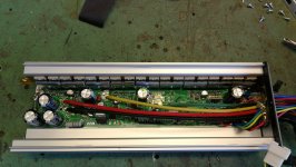
Opened the controller and investigated. Its the KT48ZWSRKT-SJT02L controller in this kit.
The 3W dropper resistor (270R) was discolored but still measured 270R, about 3.5V out from the LM317 reg, and 5V on the output of 7805 regulator was missing.
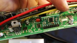
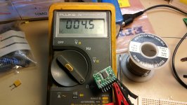
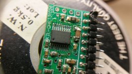
After some poking around and feeding the 5V rail with a CV/CC power supply I noticed the MCU (BS003F3P6) on the vertical board got hot. Pulling 0.5A at 1.6V from the power supply. I measured 4.5ohms across VDD and GND on this chip.
Removed the whole MCU board and the 5V is ok again.
Tried the controller using the power supply (50V/1.5A max) with this little board unsoldered and it does spin the motor but only to about 15-20km/h, than it either stops driving (freewheeling) or it just suddenly locks up the wheel pulling 1.5A and kicking the power supply in to current limiting.
Get error 03 which has to do with hall signaling.
Removing the hall signal connector completely makes the motor just tick when giving throttle.
This sudden breaking problem worrys me a bit. Im thinking about what could happen if I connect the battery and try this with no current limiting. Maybe the whole controller shorts. Maybe all FETs turns on the same time and thats what makes the motor stop so suddenly and triggering the CC on my PSU...
What is the purpose of this little board, do you know? I see alot of pictures on here of the KT48 controller but none of them has this little board in them.
Im speaking to the chinese about this now and hopefully they will help me.
Maybe they send a new MCU board for replacing, or hopefully a new controller as there seems to be strange behaviour in it now.
I was trying to find a schematic of the KT controllers on the web but only found a simplified schematic/block diagram here on ES.
Is there a more complete schematic where the function of this MCU can be seen?


