Using a key switch with Cycle Analyst MF Switch (CA3_MFSwitch)

Joined
Sep 8, 2019
Messages
660
Location
USA, CA, Bay Area
I picked up the Cycle Analyst with CA3_MFSwitch a while back and I'm looking into repurposing it in a new build. On this new build I'd like to not use the "on/off" orange button, but instead wire up a key switch on the handlebar instead.

Where I'm stuck is I have no idea how this orange button achieves on/off state nor how I could bypass/replace it with the key switch.

There are older references around here and in various manuals which indicate the simple thing to do would be to reroute the V+ going into the CA through the key switch. Easy peasy...except I don't think that applies here. The CA with the MFSwitch, when it gets power, does not immediately turn on. So simply interrupting the V+, I don't think, would work.

And, I can't find any information on what, exactly, is going on inside the wiring of the CA with regards to the MFSwitch and how (what seems to be) a momentary button is creating this effect.

If anyone has done this, that'd be awesome to hear about, but I'm also interested on any inside baseball about what this MFSwitch is actually doing before I go and open up the CA myself to look.
 
I was shipped a defective MFSwitch with broken on/off switch, so I'm pretty familiar with this actually. The broken one would only turn the bike on when held down. So whatever part keeps the on/off pin connected to V+ after pressing was broken.

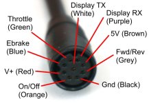
Before receiving the replacement, I was able to make my Baserunner controller automatically turn on when my battery was turned on by simply shorting the red V+ pin to the orange on/off pin on the unused 9 pin mains connector:
Baserunner_MainsPlug (1).jpg

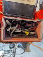
You can see the taped connector with the pins shorted at the end here:
PXL_20220925_200302579.jpg

This makes the MFSwitch irrelevant for powering on the controller and display. I just used a pair of JST pins twisted together (so essentially a paperclip or jumper), but you could easily wire a key switch to those two pins as well. As long as the key switch shorts the two pins when in the on position, your bike will be on.

It's not difficult to do the same modification at the cable between the Cycle Analyst and the MFSwitch if you prefer. You'd have to cut the cable and redirect the red and yellow wires to your ignition switch instead of the MFSwitch:
image.png

My battery has an ignition switch built in, so I never bothered. Just having these pins always shorted is fine for me since that makes the bike on when the power is on.
 
Thanks for the info; using the V+ -> onoff on the mains pin is a good idea, but I also don't want the button on the MFSwitch to work if I go that route, which I suspect it still would if I used just that.

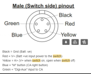
The info around this might be more useful for me:

image.png

Where did you find this pin out diagram? It's not on the product details page nor the CA details page.

With that, I might just purchase an extension and modify it to not carry the yellow cable through (so I don't have to muck up the switch/ca in the process).
 
Switch on the MFSwitch would not be able to turn the bike off if you go the mains pin route. All it does is connect what the jumper connects anyway, so it's irrelevant if it is on or off at that point. Bike would be on.

MFSwitch pin out is from email thread with Grin re the defective switch.
 
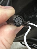
Yeah, this doesn't quite work out how I'd like. As you noted:

2023-06-09 13.03.44.jpg

Shorting these out does indeed turn on the controller. So a key switch could go here. And, once shorted, the button on the MFSwitch can't turn off the bike. However, once disconnected, the MFSwitch button works as normal *and* it keeps the system on; this I don't want.

If I leave the MFSwitch disconnected, and use the shorting above with a key switch, it'll work as I'd like (key turns on/off controller), I just lose access to the up/down buttons from the MFSwitch. I'll live with that for now (I have a POT I can use for PAS level tuning) so that'll suffice.

I suspect my original idea of a snipped extension would get me the MFSwitch and key switch combo I want, so maybe I'll chase that down at some point, but it's not worth the shipping cost from Grin until I have another order to make :D

Thanks!
 
Ah, that's true. For MFSwitch route might need to only tap red and snip yellow, though. Not snip both and route to ignition. Since switch might need red for the other buttons to function depending on how they are implemented.

Cycle Analyst supports a lot of other accessory inputs, though, from reading the manual. I'd probably just use something other than the MFSwitch in that case.
 
None of the CA inputs run off battery voltage, though, which is what the orange switch controls AFAICT, so it should be the only thing in that unit that has B+ running to it. (grin would have to say for sure unless you can open it up to verify).

According to this from the Grin page linked previously, there are two wires in the main connector at the CA that are probably involved, but it doesn't state which is input and which is output or if both are input. If the CA-WP itself is not different internal hardware than non-WP versions, then there isn't anything a second input could do, so it seems likely that one of them is an output, not an input.

Most likely the KeySw pin is an output (intended to send power to the KSI wire of a controller to provide the internal LVPS with power to run the MCU/etc), wired to the 5-pin handlebar connector's output pin from the orange button. The CA's actual B+ power probably also connects to this.

The V+ pin is probably an input, wired to the supply pin on the 5-pin handlebar connector.

There's no diagram for the 5-pin connector on Grin's site that I can find, and no internal wiring routing listed for the CA-WP between the CA and the two connectors.
1686547093006.png


The extension cable with that wire snipped is your "easiest" and cleanest solution. You can also repurpose the orange switch for something else as well, if needed, by snipping the wire that goes to it in the extension as well as the one you ahve to snip from it's output.

Alternately if you are willing to open the CA you can disconnect the wire from the CA power input that comes from the MFswitch and connect a wire to the B+ that comes off the keyswitch instead. But this is not as clean as you now have a stray wire to run out of the CA casing to wherever, possibly finding or making a new hole in the CA case to do this. :(
 
Last edited:
Yeah, this doesn't quite work out how I'd like. As you noted:

View attachment 335055

Shorting these out does indeed turn on the controller. So a key switch could go here. And, once shorted, the button on the MFSwitch can't turn off the bike. However, once disconnected, the MFSwitch button works as normal *and* it keeps the system on; this I don't want.

If I leave the MFSwitch disconnected, and use the shorting above with a key switch, it'll work as I'd like (key turns on/off controller), I just lose access to the up/down buttons from the MFSwitch. I'll live with that for now (I have a POT I can use for PAS level tuning) so that'll suffice.

I suspect my original idea of a snipped extension would get me the MFSwitch and key switch combo I want, so maybe I'll chase that down at some point, but it's not worth the shipping cost from Grin until I have another order to make :D

Thanks!
Hello, I know this is an old post. How did your key switch end up being connected? I’m looking at doing the same thing and came across this thread. Instead of going into the 9pin mains, I was going to use the V+ and gnd from the WP8 harness. Seems like that would result in the key turning the display, then disabling the power button while key is off. I’m curious how yours turned out.

Ahh, I see your new build. You have a POT instead of the MF Switch and that you have wired your keyswitch to the 9pin mains.
 
Last edited:
Back
Top