Hi,
one guy on a german ebike forum (see https://www.pedelecforum.de/forum/index.php?threads/classic-andere-akkus-durch-umbau-der-original-platine-verwenden-anleitung.23236) posted a thread on how to use a non-Bosch battery with the Bosch (classic) ebike. The idea is to take the BMS from an old Bosch battery and wire it between the new battery and the motor. This allows the Bosch BMS to communicate with the motor, something used on this proprietary system Obviously, there are other alternatives (e.g. using an external battery in parallel with the Bosch battery) and this has been discussed on the german forum too. But here I'd like to consider the idea of using the Bosch BMS with another non-Bosch battery.
The guy (Epikao) who started the thread on the german forum did not provide any details on how to build his setup and his website is no longer available. But let's discuss this setup in more details here. The point is to use any 36V battery (using its own BMS!) with a BMS taken out from a Bosch battery so that it can communicate with the Bosch motor.
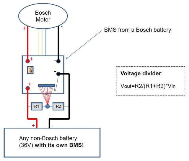
I have very limited knowledge in electronics/electricity but I was thinking about one way to do that. Basically, what we need to do is to fool the Bosch BMS into thinking it is connected to a genuine Bosch battery. First, the input wires of the BMS should be connected to the plus and minus of the battery. Second, since the Bosch BMS monitors 10 parallel cell groups individually (using a thin flat ribbon cable), it expects a signal of approximately 1/10th of the total voltage of the battery in each of these cell groups, which indicates that the cell groups are balanced. If the cell groups are not balanced, it will likely throw an error. One way to fool the Bosch BMS into thinking it is connected to a battery with perfectly balanced cell groups is simply to divide the total voltage of the battery by 10 using two resistors R1 and R2 in series, thus building a so-called voltage divider. I stress here that the Bosch BMS is only used here to allow the CAN communication with the motor. It is not used to monitor cell groups in the battery. For this purpose, the battery that we intend to use with the system should have it's own BMS!
We want to divide the battery voltage by 10 so R2/(R1+R2) should be equal to 0.1. This could be achieved e.g. if R1=9000 Ohms and R2=1000 Ohms. In that situation, the voltage taken in-between the two resistors would record 1/10th of the total voltage of the battery pack, which is what we want. The total resistance in the voltage divider is R1+R2=10’000 Ohms so if the battery is 36V nominal, the current flowing through the voltage divider would be 36/10’0000=0.0036=3.6mA. This means that the power lost in the divider would be only 10’000*(0.0036^2)=0.13 Watts, which appears negligible and should not generate any heat.
With this setup, all indications (incl. battery charge level and range) in the Intuvia or HMI consoles should be correct and any non-Bosch battery (36V) with its own BMS could be used to power the ebike. What is necessary though is to find a suitable connector with 10+1 wires that connect in place of the ribbon cable. The 10 red wires should be connected to the point in-between the two resistors and the last black wire should be connected to the negative so that all 10 wires record a nominal voltage of 3,7V. Below is a picture of the setup:
Now a few questions:
1) Do you think this setup would work or am I missing something?
2) Is this okay to use high resistances for R1 and R2 in order to minimize power losses through the voltage divider or does this lead to some issues? Basically do you think that R1=9kOhms and R2=1kOhms represent appropriate values?
3) Is it possible to source an aftermarket connector with 10 (or 11) wires that can be connected in place of the ribbon cable? Or is it possible to re-use the ribbon cable in some way?
4) The green and yellow cables are for the CAN communication. What is the purple wire used for? Is it used for the charging process of the Bosch battery and can be safely disconnected when used in this setup?
Thanks for your feedback!
one guy on a german ebike forum (see https://www.pedelecforum.de/forum/index.php?threads/classic-andere-akkus-durch-umbau-der-original-platine-verwenden-anleitung.23236) posted a thread on how to use a non-Bosch battery with the Bosch (classic) ebike. The idea is to take the BMS from an old Bosch battery and wire it between the new battery and the motor. This allows the Bosch BMS to communicate with the motor, something used on this proprietary system
Obviously, there are other alternatives (e.g. using an external battery in parallel with the Bosch battery) and this has been discussed on the german forum too. But here I'd like to consider the idea of using the Bosch BMS with another non-Bosch battery.The guy (Epikao) who started the thread on the german forum did not provide any details on how to build his setup and his website is no longer available. But let's discuss this setup in more details here. The point is to use any 36V battery (using its own BMS!) with a BMS taken out from a Bosch battery so that it can communicate with the Bosch motor.
I have very limited knowledge in electronics/electricity but I was thinking about one way to do that. Basically, what we need to do is to fool the Bosch BMS into thinking it is connected to a genuine Bosch battery. First, the input wires of the BMS should be connected to the plus and minus of the battery. Second, since the Bosch BMS monitors 10 parallel cell groups individually (using a thin flat ribbon cable), it expects a signal of approximately 1/10th of the total voltage of the battery in each of these cell groups, which indicates that the cell groups are balanced. If the cell groups are not balanced, it will likely throw an error. One way to fool the Bosch BMS into thinking it is connected to a battery with perfectly balanced cell groups is simply to divide the total voltage of the battery by 10 using two resistors R1 and R2 in series, thus building a so-called voltage divider. I stress here that the Bosch BMS is only used here to allow the CAN communication with the motor. It is not used to monitor cell groups in the battery. For this purpose, the battery that we intend to use with the system should have it's own BMS!
We want to divide the battery voltage by 10 so R2/(R1+R2) should be equal to 0.1. This could be achieved e.g. if R1=9000 Ohms and R2=1000 Ohms. In that situation, the voltage taken in-between the two resistors would record 1/10th of the total voltage of the battery pack, which is what we want. The total resistance in the voltage divider is R1+R2=10’000 Ohms so if the battery is 36V nominal, the current flowing through the voltage divider would be 36/10’0000=0.0036=3.6mA. This means that the power lost in the divider would be only 10’000*(0.0036^2)=0.13 Watts, which appears negligible and should not generate any heat.
With this setup, all indications (incl. battery charge level and range) in the Intuvia or HMI consoles should be correct and any non-Bosch battery (36V) with its own BMS could be used to power the ebike. What is necessary though is to find a suitable connector with 10+1 wires that connect in place of the ribbon cable. The 10 red wires should be connected to the point in-between the two resistors and the last black wire should be connected to the negative so that all 10 wires record a nominal voltage of 3,7V. Below is a picture of the setup:
Now a few questions:
1) Do you think this setup would work or am I missing something?
2) Is this okay to use high resistances for R1 and R2 in order to minimize power losses through the voltage divider or does this lead to some issues? Basically do you think that R1=9kOhms and R2=1kOhms represent appropriate values?
3) Is it possible to source an aftermarket connector with 10 (or 11) wires that can be connected in place of the ribbon cable? Or is it possible to re-use the ribbon cable in some way?
4) The green and yellow cables are for the CAN communication. What is the purple wire used for? Is it used for the charging process of the Bosch battery and can be safely disconnected when used in this setup?
Thanks for your feedback!