Using RC motors on E-bikes [Archive]

Status
Not open for further replies.
you could just use a lower turn motor, and not apply full throttle on hills, its the same as full throttle with more turns, but on flat ground you can go faster. if you had a single turn of fat wire, then you get a lot of rpms and little torque. if you want the motor to handle hills then pretty much your only choices with a hub motor are to use a smaller wheel or go slow. this is why i dont use a hub motor on my bike. i want it to go faster than normal, but i wouldnt have fine control over where the motor is running in its power band, so if i overvolted it it would be running overloaded, when you overvolt, you need to increase the gear ratio to keep the amperage the same and get higher power output at the same efficiency. theyre good and efficient if you use them for the power theyre designed for though. if i were you i would get the lowest turn one i could and just set up a current based throttle, just remember less turns is the same as more voltage, so no need to get a high turn motor and be dissatisfied with the power and have to buy more batteries to increase voltage.
 
lawsonuw said:
HAL9000v2.0 said:
"Futaba J standard" is 0-5V control or something else?

"Futaba J" is a 'standard' pin out and connector body for RC components. The actual signaling system uses is common to all RC components. The signal consists of a 1-2ms positive pulse 50-70 times a second.

Marty


So If I understand this correctly , frequency of pulses is proportional to rpm? 50 is min and 70 is max or this is just tolerance width?
 
Thats the key! Eureka! Fewer turns mean more voltage for the same performance! Uh, I think! :oops: Thats why the old racing Astroflight motors had very few turns of heavy wire and could turn tiny props real fast, but the ones for big high pitch props had many turns of thinner wire!
otherDoc
 
If we go back to the RC motors again I think the point about them is that you can spin the motors really fast and since:

Power = Torque * Rpm

...if you increase the rpm with a smaller torque you still increase the power. Changing the internal configuration of the turns of the motor tends to have tradeoffs, but increasing the rpm has little in the way of tradeoffs except that now you have a monster of a motor as far as high rpm to deal with. The only negative about high rpm RC motors is that you need to gear it down all that much further.

Part of the reason hub motors are so heavy by comparision (the heaviest can be 25 lbs compared to the RC motors that weight only a few pounds) is that they only turn at a speed of at most 500 rpm. In order to develop any power with such low rpm you need lot's of metal.

So let's reaffirm the brilliance of the core concept... high rpm gives more power while needing less weight. 8)
 
safe said:
So let's reaffirm the brilliance of the core concept... high rpm gives more power while needing less weight.
Or...
Small motors require high rpm to produce high power.
Small motors require transmissions to be useful.

:lol:
 
HAL9000v2.0 said:
lawsonuw said:
HAL9000v2.0 said:
"Futaba J standard" is 0-5V control or something else?

"Futaba J" is a 'standard' pin out and connector body for RC components. The actual signaling system uses is common to all RC components. The signal consists of a 1-2ms positive pulse 50-70 times a second.

Marty


So If I understand this correctly , frequency of pulses is proportional to rpm? 50 is min and 70 is max or this is just tolerance width?

It is pulse width that the RC controllers look for.

TD,

Yes, that is the issue with RC motors. However, I think a simple reduction unit can be made (I am working on it) that would be relatively easy to work with and not too expensive. But, by the time a motor and reduction unit is built or bought, you could buy a hubbie. There are benefits and drawbacks to both.

Matt
 
recumpence said:
Yes, that is the issue with RC motors. However, I think a simple reduction unit can be made (I am working on it) that would be relatively easy to work with and not too expensive.
Absolutely... I expect efficient, lightweight trannys to become conventional.

I also would welcome the development of modular multi-motor systems. They might weigh more than trannys, but costs could be significantly lower. 8)
 
TylerDurden said:
recumpence said:
Yes, that is the issue with RC motors. However, I think a simple reduction unit can be made (I am working on it) that would be relatively easy to work with and not too expensive.
Absolutely... I expect efficient, lightweight trannys to become conventional.

I also would welcome the development of modular multi-motor systems. They might weigh more than trannys, but costs could be significantly lower. 8)

The best option (easiest) for a multi motor system would be a oneway on the motor shaft for freewheeling of that motor when not driven. It could function like the newer cars' multi cyclinder systems with a few cylinders shutting down at low load for better efficiency. The same could be done with a multi motor system. Two motors could be run for accelleration or high speed, but only one when less power is needed.

Matt
 
John in CR said:
If this is all true, then we should just have single turn coils with big fat wire, and just gear accordingly. In the above example, equal amps in at equal voltage (ie same power in) then less heat means greater efficiency, however, even at equal efficiency same power in means same power out. If the rpms are lower then there has to be more torque, just like changing the gear ratio.

Something definitely doesn't jive with the explanations given. Do the Crystalite torque hubbies have more turns in the windings or not than the speed hubs, or is it that they have more coils? They have a lower kV, and my impression is that at the same power in (equal amps and voltage) they will rotate slower but with more torque. I'm not talking about how much current is possible, just how much you provide.

I'm sorry if I'm being dense, but this really doesn't make sense. Once I see the light, I'll go back and delete my posts to keep the thread clean.

John


Single turn coils would work if the hub motor spun the proper wheel speed on the desired voltage, but it is MUCH easier to wind a motor with a few turns or more. For hub motor use it does not work with Crystalite's design, but if you were to gear the motor (reduce the load) you could make it spin faster without overloading it if the motor didn't sling apart.

A lower KV motor that is running at the same power (voltage and amps) will indeed rotate slower but with more torque, as compared to a faster motor. The key is that a slower motor (if geared the same) will not pull as many amps as compared to a faster motor. The motor itself will not be able to produce more torque, but gearing changes may change the torque that is needed for running at X speed or acceleration rate.


RC input is a pulse width that varies from 1 millisecond to 2 milliseconds. 1ms is no throttle, 2ms is max throttle.
 
johnrobholmes said:
...The motor itself will not be able to produce more torque...

I believe this gets down to my whole issue, the difference between "able" and "will". Given a fixed amount of current and fixed voltage, won't the motor with more turns in it's windings result in more torque at low speed? Given my current batteries, if I put a big RC motor on my bike I can't send it the amount of current it is "able" to draw, nor do I want to. At low speed during a hill climb for example, that tremendous amperage just causes problems and waste. Why wouldn't we just want more turns in the windings AND control the current going to the motor.

John
 
if the batteries are the limiting factor then yea use more turns with less current. the lower turn motor would need more current to produce the same amount of torque, but since the resistance is lower, the same amount of heat is produced in the motor and you get the same efficiency. you have two choices, for example use a 10 turn motor with a 36V battery pack with a current limit of 100A, or use the same motor with 20 turns with a 72V battery pack with a current limit of 50A. in the 36V one you could have something like 4p12s, and in the 72V one 2p24s. you get the same performance from each.
 
John in CR said:
Given a fixed amount of current and fixed voltage, won't the motor with more turns in it's windings result in more torque at low speed?
John


Yes, the higher turn motor would produce more torque if current and voltage are fixed (assuming it isn't saturated). The issue is that the higher turn motor will not pull the same amperage unless it is geared taller, the slower rotational speed of the motor on a given voltage makes it pull less amperage when gearing is fixed. When gearing up to adjust for wind differences you are still getting the same power and the same torque at the wheel, assuming final wheelspeed is the same. The act of gearing up negates the torque increase at the motor.

Think of it another way- which would have more torque at the contact patch, A 5303 laced to a 16" rim, or a 5306 laced to a 26" rim? Assuming both are running at the same voltage and final wheelspeed is the same, I can guarantee the 5303 on the smaller rim will accelerate quicker as long as it wasn't being overpowered. This is simply because we are increasing motor speed and gearing, and it is only possible when the motor has more power headroom.

Basically there are just a few main points to consider. Is the motor too hot (fast) for the max load it will see? Can the batteries and ESC keep up? If you do need more torque the only way to get it is with a bigger motor, or additional voltage if the motor is not being run at max already. To really increase torque at the wheel a combination of gearing down and voltage increase will get the job done, but this can only happen if the motor is not being run at max. Increasing wind count is just called a "torque monster" by the manufacturers when in fact it will produce less torque and power. The key aspect is that the "torque monster" winds don't overheat on long hills with big loads.


It all really boils down to stator and magnet saturation. XXXX motor can only produce so much torque. It doesn't matter what wind or configuration, the motor will get saturated at some point and stall. To increase torque we need more motor.
 
looking for ESC with current limiter ...

first I'd like to say Hi !, first time poster ,... newbee,...

questions,.... looking at the brushless ESC ,... and can't seam to find a current limit control,...
looks as, they pulse switch, the power from the battery to the motor, like an on/off switch ,
and with big caps, the current might indeed be limited.

what I'd like to find is an ESC , where I can have current limits ? is there such thing ?

why , you'd ask,... some of the motors could pull 200-1500 A
and most of be converted to heat, due rpms and loads,...
like to use small affordable batteries,...
and biggest motors that fit.

so many questions,... bare with me,
what's my start point,...
an robot motor 28-150,... 285 stall, but continuous on 24V around 20A , aka 480W,...
probably burns off around 85-100W,.... my concern is heat, and conserve batteries,...
as such like to be able to limit the current,.... like having 5A steps
5A 10A 15A 20A , and open max peak 50A
that would help limit the forces on the gearbox,...

other thoughts,... outrunners look good , but need air cooling, and I'am thinking to put this on a mountain bike,... so water, sand mud,...
and noise the robot motor is sealed,... the outrunners open, with an air wheel attached, needs more space,.. but looks like an turbo charger blade,...
and spinning over 5000rpm , with a dozen blades, would think, it sounds like one too,...

am I all wet behind my ears ? which way to go,... thanks, Rob
 
if you know a little about electronics and programming you can make a current limited throttle for any ESC with an mcu with 2 ADCs and PWM output, just wire the ESC's shunt resistor to one ADC or add one if it doesnt have one. you can wire a hall effect throttle to the second adc and use it to generate a 1-2ms pulse to go to the ESC, it just lowers the throttle when the current goes over the limit. you only need a few components do build the whole thing, it would be under $10 id say. it wouldnt have great response time but it would work.
 
thanks ,.. but not that good at programming,... and having a mcu with adc,... to much for me,...
did find a sabertooth controller,...
http://www.dimensionengineering.com/SyRen25.htm
now that one is for brushed DC motors,.... at least a start without burning things up,...
wish there was an brushless ESC, with hard limit programming option,... guess for testing could solder an 50w resistor in serious,...
back to square one,... need a gearbox,... need belts, pulleys,.... and a flip flop hub sounds great,... exept I can't find a 1.375 /tap cutter,... one side bmx, other side belt,
looking at scooter motors,... for testing,... but the space between cranks is limited,... so outrunners seam to fit,....argh,... nothing seam to fit,... need a new frame from scratch to fit all that stuff,... oh the g-boxx 2 is $900 and needs a new frame,
new idea,... having a huge sproket, I mean pulley on rear wheel, so 2 step down only,.. but the chain/chainring be big and heavy,
and for a belt a 2 foot 8mm gt belt pulley is probably diecast, so thinking, if the belt does not cost an arm and a leg, to reverse it, and mount it on a tube, aka flat metal homemade tube or say a cut 20" rim, bolted on the spokes,... just an idea, that could get 20:1 in a single step
oh, need to find some strong DC motors below 3.8" length,...
for outrunners,... cobalt motors can take the heat, and reaper makes a decent one , expensive thought,
got late, gotta run, thanks, Rob
 
I don't think you need a current limiter. You just need to reduce the gearing until you don't hit ridiculous bursts. The motors won't be stalling out during the entire acceleration.

Ok, your starting point. You have a robot motor in mind. Do you have a link to it? We can help if we know the KV value and size of the motor.
 
rschultz101 said:
new idea,... having a huge sproket, I mean pulley on rear wheel, so 2 step down only,.. but the chain/chainring be big and heavy,
and for a belt a 2 foot 8mm gt belt pulley is probably diecast, so thinking, if the belt does not cost an arm and a leg, to reverse it, and mount it on a tube, aka flat metal homemade tube or say a cut 20" rim, bolted on the spokes,... just an idea, that could get 20:1 in a single step

I'm afraid that would give a different pitch, Rob. :wink:

Never mind, you're catching up fast....

http://www.motoredbikes.com/showthread.php?t=5938

For such large pulley diameters, you can often get away with a toothless pulley, even...
 
ideas,... specs

for DC brushed,...
ampflow E-150 testing, only need small battery, but ferrite
for continous use, say around 10A at 24V, with 60-70W heat
s28-150 is strong,... over 280A stall, can also run on 26V neodym,
at 24V good to 20A, with cooling, for continuous use,...
as you'd see, yeah, up to ~3.8HP,... but mostly heat, and it will burn up the motor,
so those numbers not really true,.. these are sealed, and have larger axle,..

for brushless,
HXT 80-100-B 130Kv Brushless Outrunner be a good pick, like the 130kv low rpm per volt,
bigger would be better, but this one is already 100mm plus, and crank space is limited,
- ESC 100A +, but would like one with a current limit, programmable be nice,
would like to be able to set it at 40A , 36V

thoughts, for peak or continuous use, those motors get hot, and once the magnets get fried,
efficiency goes down,... and they will produce heat instead of motion,...
so down the road some sort of cobalt motor, preferably brushless, and sealed be nice,
what does not cost an arm and a leg,...

scooter motors,... there a bunch,...
- controller is big,
- motors, big and heavy, and most of them are to big , to be mounted , between the crank
- cheap/ cheaper,...
- low efficiency

gearbox,.... the hard part,
since I'd like it on a mtb bike, target speed 7-20mph,... so 50-200rpm on wheel
target power, I'd say 100W min, 250W nominal, 600W burst 2-4min, 1200w peak burst 0.5-5 sec
torque min 8 nm, 25 nm target, 500 nm peak, burst/stall condition

with that in mind, think, we'd need a clutch, + freewheel,
softstart limit, also some sort of min speed engagment, aka bike needs to move at least 2-3mph, in motion, before engaging,
otherwise, need a downhill bike, so it does not rip appart, and with big motor , big battery, it be more of a motorcycle,...
thought of that too,.. take a dirt bike, and put a e-tek motor on, yeah like that, but would not be a bicycle anymore,
and battery and motor , be a couple of grands,..

back to drive train,
- need freewheel options
- clutch
- belt pulleys sprockets, with low profile clamps, aluminum and plastic (re enforced fiber), not sintered diecast
also , cheap once , 20-30$ , not $150+ and custom order, it's definitely a mess, let me know of a place you can buy 1 or 2 at the time,.... belts also get expensive, and tensioners too, need lightweight ones, not industrial diecast , with no bearing, gee, I don't have a couple of killowatts to spare,

notes:
there is on in the swiss, with a scooter motor and planetary reducer, but steel gears meshing together in a muddy enviroment,
is to noisy and won't last, hypoid right anglerack pinion sounds good on paper, they use it on cars, needs an oil bath, can transfere the torque, but non are available small enough,... the big stuff is way to havy, and expensive
- iron less , core less motor ,....
 
rschultz101 said:
for brushless,
HXT 80-100-B 130Kv Brushless Outrunner be a good pick, like the 130kv low rpm per volt,
bigger would be better, but this one is already 100mm plus, and crank space is limited,
- ESC 100A +, but would like one with a current limit, programmable be nice,
would like to be able to set it at 40A , 36V

thoughts, for peak or continuous use, those motors get hot, and once the magnets get fried,
efficiency goes down,... and they will produce heat instead of motion,...
so down the road some sort of cobalt motor, preferably brushless, and sealed be nice,
what does not cost an arm and a leg,...

.

Bigger also means lower efficiency at low output (higher no-load torque).

Copper fill on these (HXT80) isn't optimal, so efficiency at high loads won't be that great.

If you fry the magnets you'll need new magnets... more to the point, efficiency drops as the armature heats up ...

The Scorpion motors are claimed to have strong Neo. magnets rated to 200 deg. C. You'll have to wait until the 55mm class comes out, though.
 
rschultz10,

I am also interested in adding current limiting to my setup because I want to keep my battery current below the bms cutoff. My electronic design ability is not very good, so it would be helpful If someone had a circuit I could duplicate. So far I have not found something that exactly meets my needs. There is one that is close at http://www.recumbents.com/mars/tetz/E-Assist.htm. It uses a current shunt and an op amp to electronically lower the throttle when current gets too high. With a little modification, I think that this design could work for me. It also helps that I am using the same Astro Servo Tester.

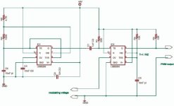
Another option is to build your own Servo Tester. This one doesn't use a micro controller. I found the circuit below somewhere on the net, don't have the link, and can't not give proper credit. The resistors/caps are not correct for a servo tester, but the equations for calculating them are on the net. This link http://www.rc-cam.com/servotst.htm gives you the pulse widths needed for the resistor/cap calculations.The R2 resistor could be replace with a 5K throttle. My thoughts are to add a current shunt and inverting op amp to feed the modulating voltage input. I think that the modulating voltage should be between 1 and 3 volts assuming the supply is 5V.

Maybe one of the more electronically endowed member can give an opinion as to the viability of my idea.

Mpja.com has 100A/100mv current shunts for ~ $7.

Bubba

pwm-pluse-555.jpg
 
a mcu design would actually be simpler than that. i wouldnt mind helping out with the code if one of you tries to build one. as for shunts, you can get SMT chip resistors on digikey for about 1.50 each, im using two 2W 0.0005R in parallel, so .25 millivolts per amp, 25mV at 100A and 2.5W. id use an op-amp to amplify the voltage across the resistors to 2V or so then feed it to the adc.
 
dirty_d,

Thanks for that generous offer. I may get back to you in the future. For now I am still experimenting with my general configuration. I need to decide if I am going to split my 48v lipo into two 24v packs and go with my current motor or possibly go with a larger motor.
 
belt pulleys and belts

where to get those ?

aluminum and plastic reenforced,
good source sdp-si.com but they don't list GT2 belts (timeing belts, poly chain gates)

need to get to 49:1 ratio, 2x3x3x2.77 = 49:1

on the last gear, thinking to use a flip flop hub ,... sealed bearings,
but how to mount a belt pulley ? cound not find a thread cutter for bmx hub 1.375 die ,

batteries, extend current rating, think by putting on low ER, capacitors,
due pulse width modulation, that could double the max current rating on the battery, up to 1/3 to 1/2 throttle,
so , what large capacitors do you put on your ESC ?

larger motors,... usually can't mount them inline with the gearbox, due length,
that would mean, need a right angle converter, spur gears are noisy,
ideal way, would be a hypoid right angle helical gear, aka christini drive, self lubricating, out of high tensile brass,
no idea where to get those,....
no beeing limited to 4" motor length , would open up the doors, for all kinds of larger and cheaper motors,...

drive train attachment, -> freewheel crank
that be the best way to attach the motor gearbox,
there are some BMX cranks with front freewheel, but only has one chainring in front,
would realy need one with a regular 3 ring spider, isis or octalink compatible,
anyone knows where to get one of those ?
 
rschultz101 said:
on the last gear, thinking to use a flip flop hub ,... sealed bearings,
but how to mount a belt pulley ? cound not find a thread cutter for bmx hub 1.375 die ,

I was able to mount a freewheel backwards on the left side of an old Shimano 3 speed hub using crude press fit machining and JB Weld epoxy! Worked fine at 42 volts for an MY1018 brushed motor. All other gears on right side, a la Currie e-zip!
otherDoc
 
Status
Not open for further replies.
Back
Top