rkosiorek
100 kW
this article gives an example of how to use a Reed Switch and a magnet mounted to the Brake lever to activate the E-Brake function of almost any controller. in my case i used the connectors for the Crystalyte controller. exactly the same connector is used on the Cyclone and Wilderness energy kits with exactly the same connections. the basic idea can be adapted to almost anything.
most controllers use a common theme for the E-Brake Line. to activate the E-Brake you short the E-Brake wire to GND or 0V. so the issue is really what is the easiest method to do that using a Reed Switch and a Magnet.
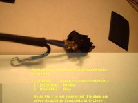
it is easiest if you use a Normally Closed Reed switch. AKA Form "B" contacts. i could not find any in stock anywhere. instead i found ones that were SPDT (both NO and NC contacts) AKA Form "C". wires were soldered on and the switches were sealed inside some thinwall 1/4" dia plastic tubes. i just sealed the ends with hotmelt glue:
View attachment 4
Brown = common
Black = N/O
Blue = N/C
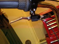
you want the NC contacts because the brake function is activated when the input gets shorted to GND. the switch is mounted to the frame of the brake lever. the magnet is mounted to the moving part of the lever. when relaxed the magnet is close to the switch holding the reed open. when pulled the magnet moves away from the switch and the NC contact will short the signal to GND.
to use the most commonly available NO reed switches AKA Form "A" you need to find some mounting where the magnet moves closer to the switch as the lever is activated. easiest place to arrange that would be to mount the magnet to the cantilever arm at the sheath covered end of the brake cable and the switch to the cable between the arms. when you activate the lever, that piece of cable shortens pulling the cantilevers together, moving the magnet closer to the NO switch and activating it.

Pin1 = not connected = V+ (on controller)
Pin2 = Brown = GND (on controller)
Pin3 = Blue = Input (on controller}
these connectors are the XS Series connectors from JST Manufacturing. they are used on the Crystalyte, Cyclone and Wilderness Energy motors. they are a very common wire to wire style connector.
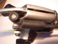
to mount my ruggedised reed switches i found some rubber molding the cross section being shaped like the letter "P". the open end has a hole just under 1/4" diameter. the switch is a tight slip fit into that hole i glued the rubber to the frame of the levers. then i glued a round magnet to the lever itself. being a slip fit i can adjust the activation point by sliding the switch inside the rubber mount. friction will hold it in place. the rubber molding was originally used as a door seal for a small portable fridge.
View attachment 2


rick
most controllers use a common theme for the E-Brake Line. to activate the E-Brake you short the E-Brake wire to GND or 0V. so the issue is really what is the easiest method to do that using a Reed Switch and a Magnet.
it is easiest if you use a Normally Closed Reed switch. AKA Form "B" contacts. i could not find any in stock anywhere. instead i found ones that were SPDT (both NO and NC contacts) AKA Form "C". wires were soldered on and the switches were sealed inside some thinwall 1/4" dia plastic tubes. i just sealed the ends with hotmelt glue:
View attachment 4
Brown = common
Black = N/O
Blue = N/C
you want the NC contacts because the brake function is activated when the input gets shorted to GND. the switch is mounted to the frame of the brake lever. the magnet is mounted to the moving part of the lever. when relaxed the magnet is close to the switch holding the reed open. when pulled the magnet moves away from the switch and the NC contact will short the signal to GND.
to use the most commonly available NO reed switches AKA Form "A" you need to find some mounting where the magnet moves closer to the switch as the lever is activated. easiest place to arrange that would be to mount the magnet to the cantilever arm at the sheath covered end of the brake cable and the switch to the cable between the arms. when you activate the lever, that piece of cable shortens pulling the cantilevers together, moving the magnet closer to the NO switch and activating it.

Pin1 = not connected = V+ (on controller)
Pin2 = Brown = GND (on controller)
Pin3 = Blue = Input (on controller}
these connectors are the XS Series connectors from JST Manufacturing. they are used on the Crystalyte, Cyclone and Wilderness Energy motors. they are a very common wire to wire style connector.
to mount my ruggedised reed switches i found some rubber molding the cross section being shaped like the letter "P". the open end has a hole just under 1/4" diameter. the switch is a tight slip fit into that hole i glued the rubber to the frame of the levers. then i glued a round magnet to the lever itself. being a slip fit i can adjust the activation point by sliding the switch inside the rubber mount. friction will hold it in place. the rubber molding was originally used as a door seal for a small portable fridge.
View attachment 2


rick

