Ventilating a geared hub

John in CR

100 TW
Joined
May 19, 2008
Messages
14,954
Location
Paradise
Ventilating direct drive hubbies has been shown to be quite effective for cooling, so I'm trying it with a Fusin geared hub. I already fit a larger bearing in the wire-side cover, so I can run larger phase wires out along the axle through an added sleeve between the axle and bearing, and not disturb the gear lubrication or introduce too much dirt and grime there. The gears themselves are beefier and with less backlash than Bafangs, so I think they will hold up to the 3-4kw I want to try to push through the motor.

I'm doing this based on my belief that geared hubs are severely thermal limited compared to the power potential of the raw motor, because other than the turbulent air flow there is no good thermal pathway for the heat. At least this will get a nice flow of fresh cool air through the motor, enabling much greater heat dissipation.

I plan to add intake vents on the wire side, and exhaust vents on the perimeter of the housing on the cylinder between the disks with the spoke holes. This leaves the gear side undisturbed. I'm soliciting opinions for the shape of the exhaust holes. The reason I bring it up it is the air flow will differ significantly from ventilation of a direct drive hub, because the exterior housing spins one direction with an ID of 112mm, but the magnet bell of the motor spins the other direction over 4 times as fast with an OD of 100mm. That puts it in close proximately with the exhaust vents on the housing.

I believe that once air gets inside the housing that the direction of the bell spinning will dominate. I want to taper the exterior of the exhaust vents to create a low pressure region from the spinning housing relative outside environment by tapering the trailing edge. I'm unclear how to shape how best to shape the interior edges of the exhaust vents. It's all aluminum and fairly thick, so I can get a nice shape to stimulate the best flow.

BTW, discussion of rocks and debris entering the motor are OT, because this hub motor will be mounted on the swingarm and drive a 3-speed hub, so it will get a protective housing that allows clean air flow.

Pics to follow,

John
 
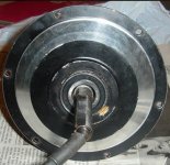
Here's the cover with the larger bearing and space for sleeve with additional phase cabling holes
Fusin cover.JPG


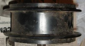
Here is the hub motor housing side and top views
Fusin hub housing.JPG
Fusin housing exterior.JPG


This is the wire side of the motor itself
Fusin motor wire side.JPG


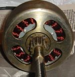
and here is the gear side of the motor sans the planetary gears and freewheel
Fusin motor gear side.JPG
 
One other thing I plan to do, if I can easily remove the magnet bell, is to take a file and shape the leading and trailing edges of each spoke (viewable in the gear side pic) to make them act a bit like fan blades to suck some air coming from the intake on the other side directly through the windings and the gap. Since it will be spinning at over 2krpms, it should pull some air.

John
 
John, do you have a pix of the planetary assembly to gauge the robustness of the gearing? Also could you run a tape measure around the housing and get the circumference between the spoke flanges for me?

I am looking for a strong, geared hubmotor to modify for an other type of drive system. Thank you.
 
I believe using a geared hub as a non-hub drive-unit (Stokemonkey-ish?) is a great idea. I agree with pulling air in through the side, and directing it out the perimeter. You could find or make something similar to this plastic radial fan (from shop vacuum cleaner, car heater fan, etc). If you do this and video a "smoke flow" test, I believe you will be pleased with the results.

biwheel.JPG
 
Yeah, a centifugal-blower type setup is likely your best bet, with vanes or cups or something on the outside to create some vacuum. I kinda suspect that any shaping on the inside won't matter very much. Since it'll be contra-rotating as you pointed out, the air movement inside will probably be pretty turbulent. That should actually be good for cooling, since it would make for good air movement over all surfaces of the motor. Anything you can do to help force air through the stator would be helpful, though. Doing a smoke test would be a good idea, to give you some idea how air is flowing in and out of the motor after your mods.
 
If something worked better than radial vanes, disc brakes would have used them by now. If you video record a smoke test of each mod for comparison, I think you will be surprised at how small and short the vanes can be made, and still have a strong effect...

2008-audi-r8-81_460x0w.jpg


I wouldn't be concerned about the interior counter-rotating flow. Air has been shown to easily and very quickly change direction. It is the whole idea behind cowl induction. Air pressure builds up in front of the windshield, then air easily makes the U-turn, but heavier dirt does not.

8188cut4inch.jpg
 
bigmoose said:
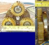
John, do you have a pix of the planetary assembly to gauge the robustness of the gearing? Also could you run a tape measure around the housing and get the circumference between the spoke flanges for me?

I am looking for a strong, geared hubmotor to modify for an other type of drive system. Thank you.

Here you go. The circumference of the housing between the spoke flanges is 38cm. Just let me know if you need something more or different pics. Since you're looking for powerful, you'll want to consider that the stock phase wires are pretty spindly (16 or 18 gauge, I think). I can't wait to see what you come up with.

John

Fusin planetaries.JPG
 
That blade shape of the centrifugal fan that SpinningMags posted is along the lines of what I was thinking to create between the spoke flanges. After thinking about it the direction the bell housing spins should be a benefit because it will get the air going in the direction of flow out between the blades, so I'll probably scar the circumference of the bell housing so it "grabs" the air better.

There is space to add some kind of vanes to the inside of the cover, and I can see how that would really stir up the flow and fling air to the perimeter. It seems like I should I brush some epoxy onto the wiring and those hall circuit boards to make sure nothing comes loose if I add some angled paddle-like vanes. My only concern regarding vanes is that I don't want to do cause a resistance to flow by creating too much spinning flow in the wrong direction. I can visualize the flow fairly well and think I'm ok, but far from certain. With a non-compressible fluid like water, I think it could be problematic, but with air I believe any increase in pressure toward the perimeter from centrifugal action will help the cause. Then the spinning bell housing will just help bend the flow in the direction of exit.

One last question. How effective could just angled holes in that cylinder between the spoke flanges be to serve as the exhaust vents? Despite being aluminum, cutting that cylinder to blade shape is going to require a lot of work with a file, though I am going to bring it to my machine shop buddy and see if he can come up with an easy approach. They're a pretty crude shop, not fully tooled like the one near my old house.

John
 
My thinking was more along the lines of the cowl hood spinningmags posted previously. You could just cut holes in the casing and then add small cowls over each one. It probably doesn't need to be anything huge, just a small, low-profile hood with the opening facing away from the direction of rotation. Having the cowls will create some negative pressure from the spinning and add to what you get from centrifugal effect. Should be pretty easy to fab something with sheet metal, or cut some plastic easter eggs in half, or something like that. I assume you don't want to increase the diameter by much since this is going to be inside your frame, so a larger quantity of smaller scoops is probably the ticket.

Also, given your planned application, you might be able to rig up some kind of ram-air scoop on the inlet side, too.
 
John, thanks for the pix and the info. I am continuing to work on another drive system for a variant on this beastie:
BomBot1sm.jpg
BomBot2sm.jpg


Thanks again for taking the time to gather the info for me! Warm Regards, Dave
 
BigMoose,

Is that for the Moon or Mars...or just what you use to cut the grass? I want one for the kids. :D

Is an additional reduction with chain and sprocket possible to get to the 25:1 you want? It looks like you'll need forward and reverse, and I understand Fusin now has a geared hub without the freewheel, for regen purposes. That would make forward and reverse possible, which isn't an option with any other geared hub that I've seen.

John
 
rhitee05 said:
My thinking was more along the lines of the cowl hood spinningmags posted previously. You could just cut holes in the casing and then add small cowls over each one. It probably doesn't need to be anything huge, just a small, low-profile hood with the opening facing away from the direction of rotation. Having the cowls will create some negative pressure from the spinning and add to what you get from centrifugal effect. Should be pretty easy to fab something with sheet metal, or cut some plastic easter eggs in half, or something like that. I assume you don't want to increase the diameter by much since this is going to be inside your frame, so a larger quantity of smaller scoops is probably the ticket.

Upon further inspection the aluminum isn't so thick between the spoke flanges, so I will have to add some material to create a centrifugal fan blade shape. I was going to leave those flanges in place, so that gives me plenty of room to create what's needed without getting ugly.

My refined plan is to swiss cheese the cylinder...nice easy and quick with a hand drill. Then rip some .75" aluminum tubing I have cutting lengthwise into 3rds or qtrs. The ripped tubing will become my centrifugal fan blades that I attach to the spoke flanges. I can either:
1. weld them in place (a trip to the machine shop with gift beer), but this would be time consuming to do well and the heat risks loosening the ring gear.
2. Quick and dirty, John style, but not necessarily ugly if I'm careful. That is to cut radial slits in the spoke flanges for attaching the blades. This is not only quick and easy, but uniformly is also simple thanks to the spoke holes. I'd cut tabs at the ends of the blades, so I can bend the blades afterward for good symmetry. Then glue the blades into the slits using an aluminized epoxy (the car metal repair stuff).

I'm really liking #2, because I can do everything without need of tooling I don't possess. Plus, I'm pretty sure I'm fine with the epoxy attachment up to the maximum 1krpm the blades will see, and I end up with a true centrifugal blower sucking air into the motor. A little paint afterward will make it look slick too. I'm getting a bit excited at this approach, since it can turn out better than my usual MacGyver mo just to get the thing working.

John
 
I was actually going to suggest something like your #2. Might as well make good use of those spoke flanges! If it looks like centrifugal force will be an issue, you could always wrap some sort of band around the perimeter to hold things in place.
 
Thanks for the info John. There is a family of these "mobile sensor platforms" That one is the largest, and there are 3 smaller. I was trying to "clean up" the drive system in my spare time with a more integrated solution. In my youth, I was involved with some planetary drives from caterpillar that made for a nice compact drive solution; my goal was to do the same with an electric drive system here. If I can get around 30Nm I am more than OK for turning. Just a side project as time permits.
 
It's controlled by a PS2 controller??? Excellent choice!

In respect to gear strength concerns, if I'm not mistaken, bronze or steel after market gears are available for some models of planetary hub motors. Nylon is used to enable more quiet operation without needing the complexity thrust axis support to use helical cut gears. For a noisy track-drive application, I don't think a bit of whirring noises would be too much of a concern.
 
The big question before I start cutting is do I go with forward curves or reverse curves on the centrifugal fan blades? I'm leaning toward reverse curves because:

1. The rpms at max will still be below 1krpms, so I don't believe noise is a concern
2. Reverse will result in higher pressure, so I think that's better due to the smaller
than typical intake area. This could become more important if I go with no protective
housing with screens over the intake holes.
3. I think the reverse curve (curving away from the direction of rotation) will look a
little better, and definitely prevent the odd rock or something from entering.

After looking into centrifugal fans I'm quite exited about this method, because compared
to what others have done with good results, this should achieve more air flow by a wide
margin. From the stuff I looked at, I think at full speed (somewhere in the 600-800rpm
range) I may get in the neighborhood of 1 cubic foot of air through the motor per second.
Even only a fraction of that would seem to be a HUGE benefit over a sealed gear hub.
Let's say the fraction is small, and that's still total air replacement inside the hub every
second, even at lower speeds, so as long as I don't detract from the turbulence against
the windings and magnets, this should prove highly beneficial due to the full ambient vs
metal temp differential...meaning far greater heat dissipation.

John
 
Sounds like you've got a plan. Can't wait to see some pics!
 
With no formal engineering training I've been trying to research centrifugal fans in an attempt to optimize the plan before I start cutting on the hub shell. ie What is the effect of few larger blades vs more smaller blades, blade angles of attack, blade overlap, etc. Online searches are coming up short other than seeing centrifugal fans with all manners of blades. With cruising speeds in the 400-800 rpm range, which is fairly low speed it seems fairly critical to do it right.

One nagging thing is that magnet housing bell spinning at 4krpm in the opposite direction inside and fairly close to the slower speed housing. It seems to me that if I roughen than bell up a bit, that its effect could override the slow speed centrifugal fan, since that rotor is spinning so much faster. While the fan blades is a neat and easy little project, it seems potentially a waste of time, and just angled slits in the cylinder between the spoke flanges will get all the air flow that is possible due to the air spinning action created by the rotor to "fling" the air outward.

Any thoughts?

John
 
It seems possible that the inner cylinder may be sufficient. Is there enough gap for you to do something to provide some 'bite' to the air? Very thin paddles or something? Can't really say how much that would move - I'm an EE, not an ME. :)

It probably wouldn't hurt anything to try that first. If it's not enough, you should still be able to go to plan B and add the fan blades on the outer housing.
 
Ive studied Stirling engines and turbochargers for years, and I believe you won't have any problems with air flow quickly changing direction. I believe you should mount the outer curved vanes in the same orientation as these wooden spokes:

tino-sana.jpg
 
I've got 5-6mm of clearance, not a lot, but enough to do something. When I think about the difference in fan action of a knobby tire vs a slick tire when spun up with a motor, some kid of ridges will make a huge difference. I guess epoxy will hold well enough, so maybe some --aluminum or epoxy soaked balsa strips will do the trick and stay on at 3-4krpm. I think that installing the strips at an angle instead of exactly perpendicular to rotation could stimulate more flow through the stator, which is another plus. Some nice reverse curved blades will look so much better than just holes though, that I'll have to do that eventually.

John
 
SpinningMags,

The air won't have to change directions once the spinning rotor grabs it, because it's spinning in the opposite direction of the outer shell. With the rotor spinning 4.5 times as fast as the shell, I just wonder if the blades on the shell are necessary...or could even slow the flow.

We'll have to talk Stirlings some time. I'd love to build a free piston Stirling using the motor from a speaker as the basis of the output AC generator. My idea was to get an army of small ones working as a roof replacement. Weight the diaphragm to a 50hz resonant frequency. One the sun is up and hot enough, the thermometer triggers a short 50hz test tone to get the little heat engines working in unison. Of course, to keep it silent, you run every other row or column out of phase to cancel out virtually all noise and vibration. With speakers so highly mass produced, that part of the rig could be extremely cheap.

I've got some other designs for hot air engines with valves for which I will learn the metal work necessary to try and build. My favorite is like an Otto with fresh air intake, but also with regeneration and the exhaust near ambient temperature, making it approach Carnot. Then there's my solar collector ideas using a piece of black cloth as the collector through which the air flows through, that caused some knock down drag out arguments over at the Hot Air Engine Society after I claimed a Th of 125-150°C without solar concentration.

I'll get back to my moderate temperature solar hot air engine pursuits, once I get totally settled with this EV stuff, which is a lot more fun. Free electricity would be nice to go with it, and hopefully in the meantime Nanosolar gets production up to where we can buy their PV at $2/w or less, or someone commercializes a 3-10kw solar dish stirling that individuals can purchase.

John
 
Just an update of this project in progress for Amberwolf's benefit. Here's a pic of the current status:

Fusin ventilation jpg.JPG

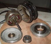
I'm going to intake air on the wire side, because I can get to the windings to add the thicker phase wires. The bearing isn't pressed into the yet. It has an ID of 45mm. The plug in the center with the holes fits onto the axle, and I'll add a key, so it won't spin. Note the holes for both bigger wires and air intake. On the left is the stock right side cover. I plan to taper the spokes of the motor's bell housing so they act like fan blades and suck some air incoming through the left cover through the windings. I may drill some holes in the solid stator to get more air through from the left. In the back is the housing the side covers attach to, as well as the spokes. The holes are cut with tapered edges, and are the exhaust.

If I don't feel like I'm getting enough air flow, then I will add blades between the spoke flanges to make that housing look and operate as a squirrel cage fan, and make the current holes bigger. Because there is flow resistance inside, I'll use a reverse curve blade, which is better for higher pressure, are quieter, and more efficient. To make the blades, I'll rip some AL tubing lengthwise into quarters. Then I'll cut angled slots in the spoke flanges to secure the blades.

John
 
Back
Top