This pack came from Bluestreak, unpacking shown here:
http://www.endless-sphere.com/forums/viewtopic.php?p=329294#p329294
It had a failure of the 4th string up, down to about 0.4V or so, measured at the balance taps. Not likely to be a simple broken balancing wire because it caused his trike to cut out (LVC?) at any real current draw.
I was suspecting a mechanical failure of cell connection inside, perhaps tab weld failures, based on the assembly of the BMS:
That melted wire and bad soldering is from VPower/CammyCC.

I decided to disassemble the pack by unwrapping the duct tape, rather than cutting it off, as this tape has nice strong adhesive *but* doesn't stick that well to it's own top surface, making it ideal for unwrapping and saving/recycling the tape itself (either in rewrapping this pack or just as bits and pieces as I need duct tape :lol
. I just used an empty tape roll to put it on, though I didn't keep it lined up with the edges very well as I went.View attachment 19
One layer of tape (about half a roll!) later, I get down to the corner-tape edges, and the cardstock protective layer.

A little struggle getting the corner tape off; I couldnt' save much of it as it tore up in little pieces. Down to the bare cardstock, now very sticky with leftover duct tape adhesive--so much so that I had to wiggle it to pick it up off my table. :lol:

Peeling the cardstock back took a little doing in places, as there is a LOT of glue (hotglue I suspect, haven't tested the theory) in crisscross lines securing it to a *second* layer of duct tape underneath.

I suspect that based on the way it peels away from the duct tape on the four large sides but not on the two small, that it was applied directly from the glue gun on those two small ends to the tape, with the end pieces of cardstock then pressed onto the glue. The glue was probably applied directly to the cardstock on the larger sides, and then folded over onto the tape underneath.

There's pretty much no way short of ripping the tape up to remove it from the ends, so I decided to leave it in place for the entire pack at this stage,
View attachment 14
especially as you can see the cardstock dividers that separate the two halves of the pack
View attachment 13
so I don't have to guess where things begin and end.
It's also clear where the balancing wires go in, and that they lay under the top layer of this duct tape

(and that there is at least one nicked wire there, from the original pack build AFAICT). Given that, I decided I would not peel the rest of the tape off, but leave it as-is, and just trace the two balance wires on either end of the bad string,

then cut away the tape around that string so I could diagnose it

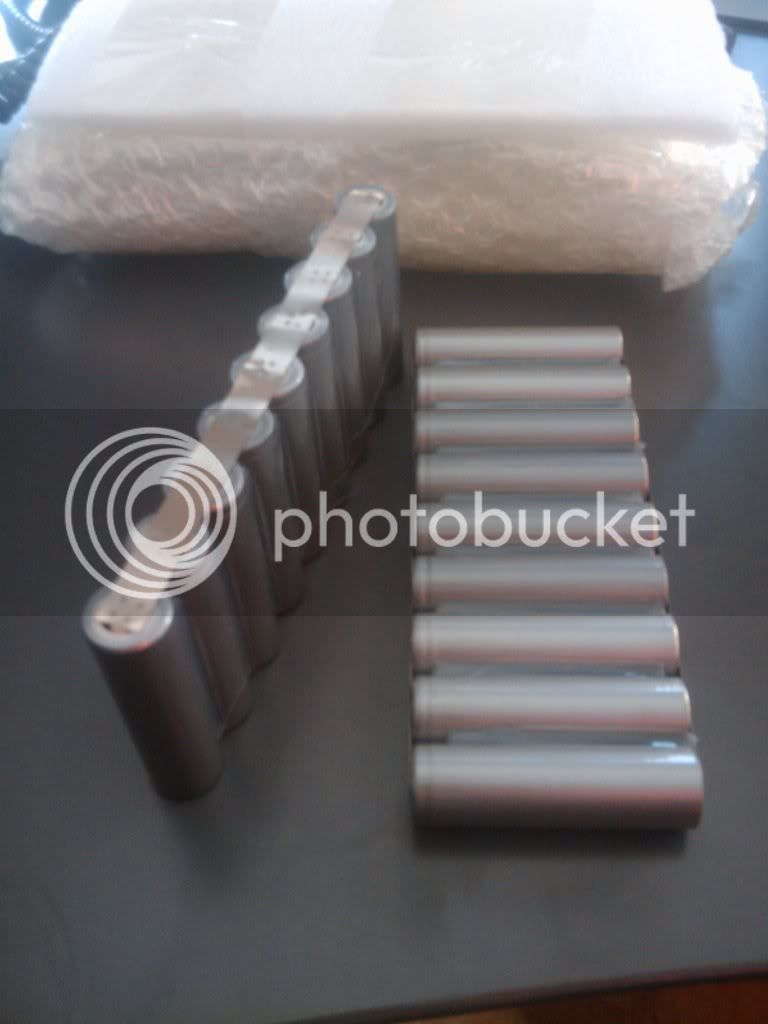
I'm holding the two balance wires there, plus the tape away from the cells. Turns out they use 18 parallel 18650-sized cells, presumably 1.1 or 1.2Ah each.

The "top" two rows in that pic are the problem string. I tried to just peel the series-connecting tabs on each end away from the problem string, but it pulled away so easily that I damaged the paralleling tab welds on the end cells of the neighboring string it was attached to, and ended up pulling the series tabs off entirely.

My 80-90W soldering iron is going to be thoroughly tested on heating this fast enough to solder it down without damaging cells. :?
I only meant to remove the series tabs so that I could test each half of the bad string to see if one was higher voltage than the other.
I found that the "top/right" half of the string is about 0.44V, and the "bottom/left" half is about 0.39V. So if there is a bad cell it's probably in the lower-voltage section, right?
Anyway, I left them that way for half-hour, unconnected to each other or anything else, but neither half recovered anything (I didn't really expect it to).
Given that plus the tab weld quality I already saw on this side, I decided I'd better take a look at the other side, seeing as a poor connection might cause something like this problem, where it doesn't charge the string right at least sometimes, and it fails to supply power to a load. I slit the tape down the whole black-lined section, and found two *more* problems, both mechanical.

The first was the balance wire you see loose in the above pic--it just fell out of the "upper" half of the pack; it goes to the end-most inside cell ends. The solder joint is not apparently very good, although you can't see it well in this pic
View attachment DSC03736.JPG
even though I circled it in red.
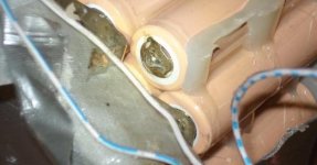
Worse, the main power output connector's crimps are terrible--they didnt' even hold the wire in when I opened the pack up and it pulled just a little on them, at the angle you see in the pic. The black came out first, and the red came out while I was holding the connector trying to see into the black heatshrink to see what had happened.

The crimps basically aren't crimped at all. It almost looks like they just pushed the wire into it, then heatshrunk around it hoping that would hold the wire in.

If Bluestreak had had to unplug/replug that BMS-input power connector more than a time or two, I expect it'd've come apart in his hands like this.
Anyway, I checked the other side (forgot a pic) and found no tabs broken off of cells or anythign AFAICT. So I started voltage testing individual cells, after having very easily pulled the paralleling strips off on the negative (outside) ends. I tested each cell in both halves of the string, and found my earlier measurements about the same for every cell in each string, whcih I didn't expect.

I thought I'd end up finding only a cell or two or few that were still the lower 0.39V, and the rest at the higher 0.44V.

So the only good way to test these was going to be to apply external voltage to them, and see if they charge up, or react normally vs in unusual ways.
First, I simply set my little Sorenson to 500mA at 3.60V, and hooked it's positive plus meter positive to the positive paralleling tabs for this string. The negative side of the Sorenson and meter I clipped together, and applied to each cell's negative end for 30 seconds while watching the meter.
In doing so I found only one cell that reacted differently.

Each of them except that cell slowly climbed to about 2.6 to 2.7V, just as 30 seconds was up. The X-marked cell climbed in about 4 seconds to 3.6V, same as the Sorenson was set to, so it is probably dead.
I am now individually charging each of the other 17 cells at the same Sorenson settings for 30 minutes per cell, to see what voltage they reach and then will leave them for a while and see what they drop to, or if they hold that voltage.

After I took the pic I decided to dig out the Fluke and use that instead, as it in theory is more accurate than the one in the pic, and that may matter in this case.
It'll be a while before I have them charged up this way, at least 8.5 hours, and then I will probably be trying to sleep to get up early in the morning, so likely no new news on this for at least another day. I might not even finish charging them up before I have to sleep.
.