What's the yellow "CH-" terminal wire on Headway LiFePo4?

ryan

10 kW
Joined
Dec 3, 2009
Messages
638
Location
California Bay Area
My setup currently looks like the following diagram, but I'm having a few problems.

1) Small Powerpoles come loose
While the larger gray Anderson Powerpoles are fantastic, the smaller ones are unclipped really easily. I've resorted to using zip ties to hold them together -- one small loop on each wire behind the powerpole, and one larger one linking the loops to hold them tight. But this makes it semi-permanent and any debugging requires clipping and relooping the zip ties. What else do you recommend? I've also considered putting larger, stronger red & black powerpoles (SB50) on each terminal and ignoring the +/- on them and wiring for charging and as a series. What do you think?

2) What's the Yellow Wire for? (CH-)
My Headway packs came with a yellow wire out of the negative terminal marked "CH-". Any idea what that's for? I just left them taped off.

3) Any other recommendations?
This is my first build and I could use any other advice you have.
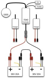
bike-wiring.png
 
Here's what I was thinking if I replaced the smaller clips with larger ones...

bike-wiring2.png

Is this an improvement? Anything I should be concerned about? This still doesn't account for the yellow CH- wires.
 
In thousands of miles, my small andersons stay connected pretty good. Mabye your wiring is too short or something about it results in a pull on one end?

The zip tie idea is brillant though, so long as your andersons aren't the on off switch to the controller.
 
Thanks I just purchased a whole lot more powerpoles to mix-n-match. I think part of the reason the smaller ones are loose is because they're not paired. I can't pair the + to -, but I can pair the likes to likes. Hopefully that will strengthen things.

Any other ideas? What about the yellow wire? Any thoughts on that?
 
i had the same problem with anderson clips so i ditched them and made a terminal kida set up.. Im really liking this way and only cost 4 dollars

1269053357.jpg
 
i found that the andersons jump apart easily if the little dogeared part inside doesn't seat all the way in and the end doesn't clip over the end of the spring underneath.

also you have to use the C- lead to connect to the negative terminal of the charger. don't charge your pack through the black wire that goes to the controller, use the charger negative (C-) lead to connect to the charger black wire. otherwise you can cook your battery pack.
 
I'm a bit confused by "Headway Lipo".

But if you are running Headway LiFePO4 with a Headway BMS, the yellow one is the charger negative. You do not charge through the discharge negative.

The yellow goes to a different portion of the BMS. I assume it activates balancing, but have never been able to prove that.


Read the labels on the BMS circuit board, if you can see it.
 
mark, the C- lead goes through the charging FET. the source leg of the charging FET is connected to the negative terminal of the charger through C- and when the BMS detects a cell going too high, then it turns off the charging FET by dropping the voltage on the gate to zero, and the FET is now an open switch and the charging current no longer can flow to the pack which is connected to the drain of the charging FET.
 
It looks in your wiring diagram that you've go the negative leads mixed up. The charger negative should go the the yellow (CH-) lead on the battery.......
 
connect the charger negative wire to the CH- on the BMS. connect the charger positive to the battery positive.

connect the P- terminal of the BMS to the negative terminal of the battery Pack.

connect the negative wire from the controller to B- on the BMS.

connect the red wire of the controller to the positive terminal of the battery. how hard can it be?
 
Back
Top