Why more KV = more power, the Maximum Power Transfer Theorem

The 5V of BEMF is caused by the RPM of the shaft which is performing work on something. That work requires power which it is receiving from the shaft. Power at the shaft is voltage times current. There is 15V of voltage headroom left to add more power to the motor.

Nope, that’s still not clear. BEMF is not performing shaft work, and it’s not doing electrical work as it’s not driving current. Compare this to mechanical work that needs both force and distance to do work.

maybe you mean it lowers available voltage (that is part of the input power) that might do work. But this cannot be true as max efficiency could never exceed 50% in this case. Plenty of motors do 80-90% on the dyno so the way it works has to be like this :wink:

(calculation does not take losses into account so we can only go lower than the calculated efficiency in real life)

Never thought about how BEMF comes into the power equations before.

An example:
kV 10 (just number to play with)
Voltage 10 (just number to play with)
Max rpm 100 (calculated)
Rpm at max power (half of the full rpm)= 100/2= 50
Voltage needed to reach 50 rpm: 5V (remember controller doesn’t need to apply full voltage to reach this rpm and a BLDC controller with PWM is not a short circuit)
Stall torque 10 Nm (just number to play with)
Torque is half the stall torque at max power = 10/2=5Nm
P=M*n/9.55 (torque-power equation)
Max power is then 5*50/9.55= 26.2W
Effective voltage to drive current=5V
Torque constant is 9.55/kV Nm/A so 5Nm needs 5/(9.55/10)= 5.2A input current
Eff=pout/pin= 26.2/(5*5.2)=100%-ish due to rounding error
 
larsb said:
The 5V of BEMF is caused by the RPM of the shaft which is performing work on something. That work requires power which it is receiving from the shaft. Power at the shaft is voltage times current. There is 15V of voltage headroom left to add more power to the motor.

Nope, that’s still not clear. BEMF is not performing shaft work, and it’s not doing electrical work as it’s not driving current.

I marked part of your statement in bold which is appears to be the issue as there is current flow. The generator is producing 5V of BEMF, the 5V is flowing out of the motor, fighting the input voltage. Kirchoff's current law / conservation of charge shows that 150A in = 150A out of a circuit. If we have 5V generated and 150A of current flowing through the coils, then the generator is producing 5V*150A = 750W of power.

Forget about PWM or losses, they are irrelevant to the core concept which is impedance matching for maximum power transfer. The supplied voltage is constant and does not vary.

Never thought about how BEMF comes into the power equations before.

Neither did I until I tried to understand this concept.

Going a bit off topic, another mind bender is realizing that all motors of the same KV produce the same torque per amp regardless of size. But this topic is better suited for a discussion on KM, the motor size constant. Its interesting. Using MPTT and KM it becomes much easier to spec a motor for a given task.
 
larsb said:
Nope, that’s still not clear. BEMF is not performing shaft work, and it’s not doing electrical work as it’s not driving current.

Noooo, BEMF produces the real power with the current component that is in phase with BEMF. In the motor model the BEMF is a voltage source in series with the phase inductance and resistance. When the current flows into the voltage source then it takes the electrical power and transforms into shaft power (motor mode), and when the current is out then it transforms the shaft power to electrical power (generator mode):
Pout = BEMF*I = M*omega (= M*n/9.55)
(without the losses)

Voltage equation for the model I mentioned (simple form for DC motor):
Vin = BEMF + I*R + L*dI/dt

More simple form assuming dI=0:
Vin = BEMF + I*R

In your example the stall torque and stall current are not independent variables, but should be calculated from the voltage equation with BEMF=0 and knowing the phase resistance that is not ignored (R):
Istall = Vin/R
Or if you specify Mstall or Istall at a given Vin then you indirectly specify R, too.

The power equation is the voltage equation multiplied by I:
Pin = Vin*I = BEMF*I + I^2*R

etc...
 
Somehow i think we are discussing different motors. BLDC motors are not driven at short circuit condition on battery voltage. Maybe you are referring to the regulated voltage?
Otherwise there are several contradictions:

The setup i run now is 72V, 5mohm phase resistance.
Istall is then 14400A calculated as per your formula
My motor kV is 60, Kt is then 0.16 and motor has a stall torque of 2292 Nm.

Except the fact that controller limits current to 300A, torque is 48Nm and that whole system exploded at the levels mentioned previously.

Voltage needed to drive 300A current at phase resistance 5mohm: 300*0.005=1.5V

Since there’s no BEMF at stall condition the PWM must lower the voltage to 1.5V to keep 300A and power input is only 450W.

On the opposite side, if current was BEMF limited from full battery current then motor would need to run at (72-1.5)*60=4230rpm to keep 300A current if inductance and switching times could be disregarded.


.
 
Yes for sure we don't want to stall a powerful motor with the battery voltage connected to it, but you can do that with small RC motors. But the theory of operation for only the motors (without controller) is the same.
If you add the controller, that will limit the current to the allowed maximum by lowering the voltage as you say, to 1.5V in stall.

We can discuss either the motor only or the motor+controller, there is the difference.
But in any case BEMF*I is the Pout. To be more precise, for BLDC the phase voltage BEMF must be taken into account, that is between a phase wire and the neutral, not the line voltage that is measured between 2 phases, and take that 3 times as there are 3 equivalent phases:
Pout = 3 * BEMFp_rms * Ip_rms = 3/2 * BEMFp_peak * Ip_peak = M*omega
(omega is the angular velocity)

The BEMF between phases (measurable easily) is the line voltage: BEMFl_peak = BEMFp_peak*sqrt(3)
 
operation will be the same but the theory explained is not possible to put into context without having controller in the picture. The classic torque-speed plot with a triangular shape will be totally different once your controller adapts an unlimited variation of drive voltages to get a limited current.

Many readers will read this thread and think that high kV motors always will provide more power.

No, they won’t. Motor has a max rpm before they burst or heat in an unacceptable way due to eddy losses.
This rpm can be reached either with low kV*high voltage and low current or high kV*low voltage with high current.

Fix one, adapt the others.
 
zombiess said:
I specified output power as shaft output power to make it more clear that it is mechanical in nature. I'm trying to separate the mechanical/electrical because a motor needs to be viewed as both a motor and a generator.

It is, but I'm not sure you need it beyond appreciating where BEMF comes from. In the past I have thought of it as a variable-impedance load, with the BEMF manifesting as changing internal resistance, with current calculable using V = IR.

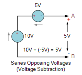
The other way is to keep the impedance as per DC resistance and subtract the BEMF from the applied voltage. E.g.

Capture.PNG

Take 10V to be your battery/controller/power suppy and 5V to be the opposing motor BEMF

10 + (-5V) = 5V

This being the true potential difference across the motor coil, represented by connections A & B.
 
Punx0r or anyone, could you write a quick explanation of how BEMF works from your understanding? Keep it simple, use an ideal motor (no loss) and treat it as an impedance. We have a miscommunication happening and I'm not quite sure where it's at.

How does BEMF limit input power? Where do the voltage and current components come from in BEMF power?
 
larsb said:
Many readers will read this thread and think that high kV motors always will provide more power.
I think that misconception (which I've never even come across) would have been dispelled by reading any of the threads delving into this topic.

> torque-speed plot with a triangular shape will be totally different once your controller adapts an unlimited variation of drive voltages to get a limited current

Yes! critical point, I think a lot of my misunderstandings have come from people talking from a theoretical motor-only POV


> Motor has a max rpm before they burst or heat in an unacceptable way due to eddy losses.
This rpm can be reached either with low kV*high voltage and low current or high kV*low voltage with high current

In my case, the top end is not even a consideration, in all cases the CAv3 (or FOC torque-throttle controller equivalent) is protecting against hitting such limits.

My concern is the heat produced by high current at the low rpm end, as I seek maximum torque without triggering those protections.

A high **battery** voltage doesn't help, since the controller is buck converting that down in startup mode or heavy loads up steep hills.

Setting the top speed reduction aside

A lower kV gives more effective low-rpm torque in that context

Right?

assuming motor not "saturated" whatever that means (ELI5?)


danielrlee said:
john61ct said:
I am in no way saying changing the kV winding does anything for performance **overall**.

What I am clear on, is that **in this use case**

- DD hub only, no gearing

- speed past 20mph is irrelevant

- heavy weight, say 450+ lbs

standing starts & long steep hills, so highest possible torque needed at well under 10mph, even 3-6mph would be worth sacrificing efficiency

heat being the limiting factor

trying to avoid a 30lb motor

** then** the low-volts / high-amps context means the kV winding makes a significant difference.

That is ALL I am saying, only within that use case, which does not apply to 99.9% of bikers out there.

And not overstating its importance, not like reducing the wheel size for example, but definitely fighting the myth that it's "always" insignificant.
I must be missing the point you are trying to make.

A certain winding might be better suited in a specific usage scenario where other parameters have been constrained to a fixed value
Well not "fixed" per se, but yes, for clarity I am **only** discussing that specific scenario, and

I'm not talking about any "specific" winding, in trying to keep the "low-rpm torque vs motor weight" ratio" up as high as possible, it seems "slowest kV / winding" is what I'd need.


billvon said:
you need a higher voltage to force enough current through the windings to reach (or maintain) a given speed, since higher speeds = shorter phase on-times = shorter time to ramp current up.

there may be too much inductance to force enough current through the winding at high speed. At low speed, it's not an issue because there is more time to ramp up the current due to long "on" times for each phase.

So for real world combinations of battery and inverter, lower Kv ratings will give you more torque at the bottom end, at the expense of speed at the top end.

 
Yah, saturated motor is when stator steel cannot take more flux so stray flux and heating increase causing motor output to leave the linear relationship between current and torque.

I’m not sure you’d need a low kV winding since dd motors are already so low that it’s not hard to get full torque, common kVs can be 10 and my motor has 60 so i need 6 times the current..
 
power = torque * rpm
torque is proportional to phase current
rpm is proportional to bemf
thus, power = phase current * bemf

Maximum peak power output from a motor is reached at 50% of max speed, 50% of stall torque, 50% efficiency

This power usually isn't sustainable or achievable for larger motors like the one on larsb's bike, but for the small motors on top speed quad copters, it's definitely useful to consider.

The same peak power output applies to batteries - max peak power output from a battery is at 50% of OCV, 50% of stall current, 50% efficiency aka the same power output is also being generated as heat by the battery
 
john61ct said:

john61ct, Kv is not going to help your example. We are talking about getting peak power out of motors disregarding heat generation. Changing Kv does not change heat generation for a given torque. I think you know that and were just hoping this thread debunked that. It does not.
 
I don’t agree, can prove it too :D
https://endless-sphere.com/forums/viewtopic.php?f=30&t=102934#p1505953

In theory all is equal but in real life it has limitations. -Controller cannot be matched (within reason) to ALL possible kV and winding. It can get too big, too expensive or too complex to match a single turn motor with a controller :D
-copper fill is highest with single wire winds. There’s a penalty in higher copper losses for the lowest turn counts due to wire transits and wire bunching.

But anyone reading thinking that they need a low kV motor due to this is probably wrong - differences and limitations are small.
 
larsb said:
I don’t agree, can prove it too :D
https://endless-sphere.com/forums/viewtopic.php?f=30&t=102934#p1505953

In theory all is equal but in real life it has limitations. -Controller cannot be matched (within reason) to ALL possible kV and winding. It can get too big, too expensive or too complex to match a single turn motor with a controller :D
-copper fill is highest with single wire winds. There’s a penalty in higher copper losses for the lowest turn counts due to wire transits and wire bunching.

But anyone reading thinking that they need a low kV motor due to this is probably wrong - differences and limitations are small.

Which part don't you agree with? Just the part about all Kv's being equal? Yes I do agree that there are limits to saying that all Kv's are equal. But for john's case, I think we agree that it's not going to make much of a difference.
 
zombiess said:
Punx0r or anyone, could you write a quick explanation of how BEMF works from your understanding? Keep it simple, use an ideal motor (no loss) and treat it as an impedance. We have a miscommunication happening and I'm not quite sure where it's at.

How does BEMF limit input power? Where do the voltage and current components come from in BEMF power?

As you say, motor is also generator. Whether the device is functioning as a motor or generator is dictated by the direction of current flow to/from the battery (or similar source/sink), which depends on which has the greatest voltage.

When acting as a motor you still have a generating component - conductors are passing through magnetic fields and any flux change over time induces a voltage in the conductor. The voltage induced depends on the length of the conductor (which is fixed), the strength of the (average) magnetic field is also fixed in most motors so the only variable is velocity - motor rotational speed. This voltage opposes the applied voltage to the motor, reducing the current and the field strength in the coils.

The mechanical power (torque/speed) to generate the BEMF comes from the shaft in a generator or the armature via the coils.

thepronghorn said:
power = torque * rpm
torque is proportional to phase current
rpm is proportional to bemf
thus, power = phase current * bemf

I started typing out something similar yesterday - BEMF is a proxy measure for velocity.
 
Thank you, learning from this discussion but have a way's to go for a complete understanding. Looks like it's really about money and speed. The motor can only produce so much torque, its cheaper to get that torque with a high turn/low KV motor. if you want speed and max torque with low turn/high KV motor then thicker wires and top end/high amp controller = money.

Have I missed something?
 
ZeroEm said:
Have I missed something?

This discussion is about theory, money is irrelevant. :)

Before coming to any conclusions you need to have a solid understanding of the problem which needs to be solved and any limitations. It's difficult to make generalizations for application. There are usually multiple ways to solve the same engineering issue, but some are usually better than others depending on imposed constraints. This is why it's important to have a good working knowledge of theory and knowing how changing one variable changes another.

I learned most of my physics/engineering/math skills from Youtube videos, the knowledge is totally free if you have the interest!
 
zombiess said:
Punx0r, what conflict do you see in my example trying to show the relationship between KV and MPTT?

I have no problem with the concept of impedance matching a motor to a battery/controller/PSU for maximum power transfer

Similarly, I think it's very relevant to select motor Kv and system voltage such that a useful torque/power curve results at intended operating speed of the device/vehicle.

What I do not follow is predicting motor efficiency from impedance matching, nor BEMF dictating motor output.

I suspect things being discussed are two sides of the same coin i.e. factor A dictates measure B & C where B = motor output and C = BEMF, but that does not mean it's correct to say C causes B.
 
Punx0r said:
What I do not follow is predicting motor efficiency from impedance matching, nor BEMF dictating motor output.

I was using the efficiency to demonstrate where maximum power is transferred, that is all. When you tell someone that an electric motor makes the most power when it's loaded to 50% efficiency, they tend to balk at the idea as it's counter intuitive. I didn't fully grasp it myself until I played with some math in a spreadsheet, then it finally clicked for me.

BEMF does not dictate motor output, but it's directly related to motor output, as you said it's two sides of the same coin.
 
I think a better title would be
"why more rpm creates more power, doesn't matter if it's created with high kV or high voltage - the ultimate power balance theorem that's often unvalid due to real life limitations" :roll:

Don't care for general statements that has to be followed by more data for people to actually gain some insight and that title is still not the best?

"why max power coincides with 50% of max rpm - controller limits disregarded" would be spot on.
 
zombiess said:
When you tell someone that an electric motor makes the most power when it's loaded to 50% efficiency, they tend to balk at the idea as it's counter intuitive.

Agreed. The similar case mentioned above with peak battery power being at 50% voltage also takes some thinking about. In both cases I think a look at a graph showing voltage/speed vs. torque/current and seeing where the lines cross is a great help.

So, on Kv, high is generally good for achieving maximum power for a given system voltage, but what happens if it's taken to an extreme where motor impedance is less than your battery/controller/PSU? I think contrary to the thead title, more is not necessarily better :)
 
Peak power at 50% efficiency only becomes true when you feed the motor with maximum current. One our bikes current is greatly limited to prevent heat problems and to not be so wasteful with our battery energy. eg I'd bet that Zero tunes its emoto's in a manner that it has over 80% efficiency at peak output power.

Another misleading thing common with motor performance graphs compared to real world tuning is that we typically have current limited so that torque is quite flat until BEMF takes over the current limiting.
 
This is true. I think a lot of information out there is more relevant/true to battery-fed DC brushed motors with simple switched control.
 
Back
Top