
nastypoker4
1 mW
- Joined
- Dec 17, 2014
- Messages
- 11
I am upgrading my bike from a 1000w 48v controller to a 2000w 48v controller. The controller has this label on it.

I have connected the 3 phase wires, the 5 hall sensor wires, 3 throttle wires and put 48v to the red "key" wire.
To set it up, I had to use the "self-study" cable. I disconnected the "key" wire and the batteries. I turned the throttle and made sure everything was ready. I connected the self study wire to -V and spun the wheel by hand. I then disconnected the self-study wire and connected the key wire to live again and it spun the wheel.
When I operate the throttle, the wheel spins but it is noisy/lots of vibration. It has no actual power behind it if I try to ride but it will push me a long. With the wheel off the ground, it draws 22A @ 48v and makes too much noise just for free wheeling. If Ioad it up I can get to 40A but there is no speed at all <5KPH. With no load, it looks like it would be 10-12KPH.
When at full throttle and lowering it down, the motor will be fixed to a certain RPM and will not just fall down if that makes sense. It is like the throttle position is purely linked to the speed of the motor.
The feed to the throttle is 4.5v and my throttle is outputting 0.8v at idle, 1.5v when the motor starts and 3.5v at wide open throttle.
If I short out the reverse wires, the motor reverses but seems to operate as it should. Quietly and smoothly and drawing almost no current but it is still slow. Probably intentionally limited by the controller I imagine.
I can't think of any more useful information to help diagnose this problem. It does not help when the sellers description does not match the picture on their page and that nothing matches the actual controller!
The aliexpress page has this picture which only matches partially.
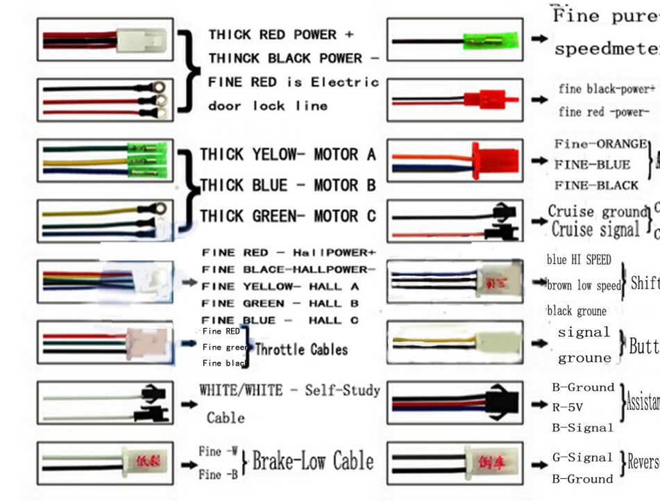
Based on testing, here is what I believe the wires are for.
A - Reversing wire + GND
B - UNKNOWN. Blue is ~7v below system voltage. One of the others is 0v and the other is 4.7v
C - Unknown
D - Self-study wire
E - Unknown. Black is 0v, Pink and brown are both 4.7v. Connecting either pink or brown to black did nothing.
F - 60-120 degree optional connector
G - 60-120 degree optional connector. Connecting F+G did nothing.
H - Speedo???
I - Key wire
J -Orange wire. Came as a bare cable with exposed copper. No idea what it does. Ignore that it is connected to something. It doesn't seem to do anything.
K - System +V
L - System -V I believe these were anti-theft power but I just used it to power the key.
M - Throttle wires
N - Throttle wires
O - Throttle wires
P - Phase wires
Q - Phase wires
R - Phase wires
S - Main battery power leads
T - Main battery power leads
U,V,W,X,Y - Hall wires. All colours match positions on the connector.


I have connected the 3 phase wires, the 5 hall sensor wires, 3 throttle wires and put 48v to the red "key" wire.
To set it up, I had to use the "self-study" cable. I disconnected the "key" wire and the batteries. I turned the throttle and made sure everything was ready. I connected the self study wire to -V and spun the wheel by hand. I then disconnected the self-study wire and connected the key wire to live again and it spun the wheel.
When I operate the throttle, the wheel spins but it is noisy/lots of vibration. It has no actual power behind it if I try to ride but it will push me a long. With the wheel off the ground, it draws 22A @ 48v and makes too much noise just for free wheeling. If Ioad it up I can get to 40A but there is no speed at all <5KPH. With no load, it looks like it would be 10-12KPH.
When at full throttle and lowering it down, the motor will be fixed to a certain RPM and will not just fall down if that makes sense. It is like the throttle position is purely linked to the speed of the motor.
The feed to the throttle is 4.5v and my throttle is outputting 0.8v at idle, 1.5v when the motor starts and 3.5v at wide open throttle.
If I short out the reverse wires, the motor reverses but seems to operate as it should. Quietly and smoothly and drawing almost no current but it is still slow. Probably intentionally limited by the controller I imagine.
I can't think of any more useful information to help diagnose this problem. It does not help when the sellers description does not match the picture on their page and that nothing matches the actual controller!
The aliexpress page has this picture which only matches partially.
Based on testing, here is what I believe the wires are for.
A - Reversing wire + GND
B - UNKNOWN. Blue is ~7v below system voltage. One of the others is 0v and the other is 4.7v
C - Unknown
D - Self-study wire
E - Unknown. Black is 0v, Pink and brown are both 4.7v. Connecting either pink or brown to black did nothing.
F - 60-120 degree optional connector
G - 60-120 degree optional connector. Connecting F+G did nothing.
H - Speedo???
I - Key wire
J -Orange wire. Came as a bare cable with exposed copper. No idea what it does. Ignore that it is connected to something. It doesn't seem to do anything.
K - System +V
L - System -V I believe these were anti-theft power but I just used it to power the key.
M - Throttle wires
N - Throttle wires
O - Throttle wires
P - Phase wires
Q - Phase wires
R - Phase wires
S - Main battery power leads
T - Main battery power leads
U,V,W,X,Y - Hall wires. All colours match positions on the connector.


