Wiring problems

a.miller

1 µW
Joined
Aug 19, 2023
Messages
1
Location
Pensacola FL
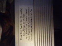
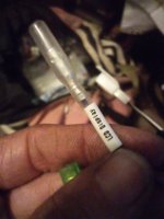
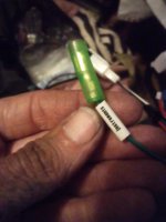
First 3 pictures are controller and the one display wire and instrument wires.
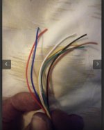
Last picture is the s866 Led display wires.
The controller came with a display (not display in pic) but it keeps reading error that says it's not receiving data. Basically same set up as this one that's on pic.
The controller in pic has labels for throttle, study wire, alarm power supply, reverse, cruise, power, 3 phase wires, hall wires, 3 speed wires,low and high brake, alarm wire, instruments, and display .
What connects to the instruments and display wire?
Also where do all the wires to display go?
 

Attachments

  • IMG_20240323_210442.jpg
    IMG_20240323_210442.jpg
    2.4 MB · Views: 14
  • IMG_20240323_210551.jpg
    IMG_20240323_210551.jpg
    2.5 MB · Views: 13
  • IMG_20240323_210601.jpg
    IMG_20240323_210601.jpg
    2.4 MB · Views: 13
  • IMG_20240323_210756.jpg
    IMG_20240323_210756.jpg
    2.8 MB · Views: 14
Last edited:
Is this a repair, or a new build?

If it's a repair, what was originally wrong that caused parts to be replaced, and which parts are being replaced?

If it's new, were all the parts purchased together as a kit, or were they from separate places, or were they used, etc?

Links to the pages each part was purchased from could be helpful to help you determine the correct wiring.

Beyond that, I can suggest looking thru my posts from the last few days for a thread where someone is trying to replace a controlelr only out of a display/controller set that came on a bike, it is directly applicable to your situation and will tell you why you can't do what you want with the parts you have.

I've also posted over the years in many other controller-wiring/replacement/et cthreads with other info, general and detailed, about this type of thing, that probably have useful info for you.

There may be some posts about the S866 (or similar displays) that show images of where the different color wires are connected inside them, but not all companies use wire colors consistently.

So...we can't really know for certain what any of those wires are for from just the provided info, but hopefully these may help.
 
Blue, yellow, and green are your halls sensors wires… Black is ground and red is 5v. The white wire normally is a temperature sensor or speed sensor wire.
According to the OP, those wires in the image in your post (and theirs) are for a display, which won't have any of the signals you mention. ;)
 
According to the OP, those wires in the image in your post (and theirs) are for a display, which won't have any of the signals you mention. ;)

Yeah and I noticed it has a brown wire as well so maybe it is for the display. Sure looks Close to the hall sensor wires that plug to the motor.

The original poster needs take a picture of the entire controller so we can see all of the wires coming out of the controller.
 
I know that my S866 display only works with a brainpower controller. I don't see brainpower on the controller label. You'll probably get a comm error with the S866.

Displays often have the same pinout on their connectors, so they will plug into foreign controllers and often be able to start them, but unless they have an agreed method for sending signals on their data busses, you get com errors.
 
with the controller powered on and connected (to battery, motor and throttle) I'd check the voltage of the "LCD display" wire. if it's a steady voltage (5 or 12, or whatever the battery voltage is) is useful information, or if it's a digital signal wire that somehow needs interfacing with the display.
however, it seems that you've already connected the display to the controller without killing either, which is fortuitous. I'd be interested in a picture of the display and how it's wired up.

one of the first "lessons" for me was not expecting to have any kind of display unless it came with the bike/controller. Luckily, since I don't care for pedal assist and like to modulate my motor contribution via throttle, this has not been too hampering for me.
it occurs to me that I have no idea how to adjust pedal assist levels without some kind of display-controller interface.
I have a speed computer for $2 from aliexpress, and a DC power meter (the 100A varieties that display current-i.e. momentary- voltage and amperage, and the amp hours and watt hours consumed) between my battery and controller

however, the lack of information and lack of standardization (they're kinda mutually inclusive) regarding display protocols and lack of even MILDLY COMMON PRACTICES for wiring/pinouts is one of my bigger beefs with this industry.
 
The controller came with a display (not display in pic) but it keeps reading error that says it's not receiving data. Basically same set up as this one that's on pic.
Do you have a link to the display/controller combo you purchased and describe how the original display was connected.
 
Back
Top