Yet another Lebowski + Honda IMA inverter & step-by-step

@kiwifiat Sorry if this a question with an obvious answer.
In this thread I see a newer version of the Lebowski board you designed that looks to be designed to drop directly onto the standoffs of the IMA inverter.
looking through other threads the best I have been able to find is the small Bobc board style. Not the one like is used in this thread.

The board has support for the resolver fitted to the HSG, just connect and tune. The board gerbers haven't been released yet as there is a revision in the works that makes connecting to the outside world less of a hassle. The current design is meant to connect to the existing oem 20 pin socket, seemed like a good idea at the time, but it is ridiculously time consuming.
 
Makes me think it's some fundamental property of motors rather than an actual controller issue and that the problem is just masked rather than fixed by "tuning". Possibly at the expense of performance in each region.

I wonder if @Lebowski has any insight into this.
IMO the issue is that HALL sensors are crap, especially when they are reliant on magnetic fields and they are placed in a lightning storm of magnetic fields that vary with phase current. The best solution was that proposed and solved by ES member Bertie using optical sensors that are impervious to changes in magnetic fields. That said I have had zero issues with the Lebowski controller with transition from sensored to sensorless operation on my old scooter that was fitted with a gen1 QS273 motor and HALL sensors. Those that I am aware of who were having transition problems traced the issues to sub-optimal alignment of the magnet on their RLS encoder fitted motors.
 
Hall sensors are indeed finecky… the best is when they are external to the motor and do NOT see any magnetic field from the coils. This is the case I think I used for my controller. The case where the sensors see the field of the coils is fundamentally different…

It would cool to take the time to make a useable-for-everyone version of the ‘sensorless from standstill’ algorithm as this is far superior. Who knows, hopefully I have time to get back into this in the near future.
 
Last edited:
Hall sensors are indeed finecky… the best is when they are external to the motor and do NOT see any magnetic field from the coils. This is the case I think I used for my controller. The case where the sensors see the field of the coils is fundamentally different…

It would cool to take the time to make a useable-for-everyone version of the ‘sensorless from standstill’ algorithm as this is far superior. Who knows, hopefully I have time to get back into this in the near future.
Does your sensorless from standstill work for all motors? Or does it require a degree of salience?

I read and understood the paper (I think), but noted that you have orders of magnitude more sensitivity in your hardware than normal FOC controllers due to the high pas filtering opamps. In my world, I created SFS that works with many motors but relies on running an angle error correction based on the Id Iq currents induced by VdVq injection. It is very very good for some motors and totally hopeless with others.
 
It requires some small degree of saliency cause thats what the principle is based on. I added the opamps to increase sensitivity (amplification) but also the be able to detect saliency while applying large torque producing phase currents (filtering).

You can do without the opamps when you have audio quality AD converters, but I want to use a microcontroller with the ADC’s inside. Also then you need lots more processing power to do all the filtering in the digital domain… and this is all assuming there’s no harmful aliasing.
 
Last edited:
The board has support for the resolver fitted to the HSG, just connect and tune. The board gerbers haven't been released yet as there is a revision in the works that makes connecting to the outside world less of a hassle. The current design is meant to connect to the existing oem 20 pin socket, seemed like a good idea at the time, but it is ridiculously time consuming.
Awsome news.

Is there any sort of expected ETA on the revision?
I understand it's a hobby project you probably work on as and when in free time so no rush. Just would be nice to know if I'm shelving it temporarily for a few months or going full cold storage for year +.

As a thought in the connector location, you could place a circular mill spec style connector on ether the back or the side of the case. Some difficulty with removing the lid I suppose. Other option is just cutting the OEM connector off the board and mounting a new connector in its place. Side mount bolts through the PCB provided the traces under it are non essential. Still a lot of messing around but less then re useing the OEM one.

I spose if the new board revision has THT wire breakout points and a provision for an on board connector that gives the most options for least effort.

Thanks again to everyone's combined effort here. It's great to see what a community can produce when It works together.
 
I will be using a 23 pin Ampseal header. Early April as a wild guess for an ETA. I still have one populated V1 board available from the initial run of ten, pm if you are interested.

Cutting the oem socket out is painful as it is screwed in from below the PCB with no access to the screw heads. I cut one out with a dremel and it created a hell of a mess.
 
It requires some small degree of saliency cause thats what the principle is based on. I added the opamps to increase sensitivity (amplification) but also the be able to detect saliency while applying large torque producing phase currents (filtering).

You can do without the opamps when you have audio quality AD converters, but I want to use a microcontroller with the ADC’s inside. Also then you need lots more processing power to do all the filtering in the digital domain… and this is all assuming there’s no harmful aliasing.

I got it working with pretty big phase current (160A). Had about 2/3 my weight on the bike saddle. I'm 90kg. Unfortunately it's only silent because I'm running 35khz pwm so half that from positive and negative injection is 17.5kHz

Something worth noting is that if you construct your injection and reading right you find that higher current stabilises the lock in, whereas other combinations are unstable with higher current.

Injecting equally in d and q axis and choosing the polarity of the q to be counter to the current is stable. If q injection is towards the current, then higher q current causes q saturation which ultimately removes the apparent saliency.

Iirc from your paper your reconstructing an entire circle from the injection, and you can see the saliency from the ovalness (very crudely transcribed). As you apply more and more torque, the circle gets less pointy on the high current q axis side. The saturation shift with current enables the 180 degree disambiguation... Effectively I just chose a single point on that circle that seems relatively unaffected by current and track that. Maybe that works well on your opamp free hardware?
 
Last edited:
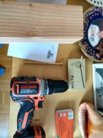
For my testing I used a drill
IMG_20180719_174224734_HDR_Original.jpeg
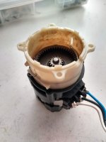
The idea was to be able to run the big screw fully into and out of the block of wood, sensorless and from standstill. So even stopping for the last cm, and then re-starting from sensorless. The motor was pretty small
IMG_20180720_083109556_HDR_Original.jpeg
I ran it at 50A phase current. It worked flawlessly. Never tried it on a bike as here the law is too strict now for home brew.

From your short description I don’t get what you’re trying to do…
 
Controller is re-installed on the bike after sealing and additional connectors (see 7).
I did an extended test run (emulated commute on Sunday evening, up to 90km/h and 20°C->~40°C in the uphill leg) and deemed it safe to commute for real today. See my build thread as well.
View attachment 337049View attachment 337052
However I'm still struggling with the launch performance. Once it reaches 15 km/h and FOC kicks in it's smooth and seems to deliver full power up to the configured limits.

Post initial configuration with Roger the journey was as follows:
  • transition to FOC was rough & unreliable at 1500 eRPM
  • dropped phase current from 300 to 150A, re-autocompleted at 200A (for higher error currents) and items further down then just reduce phase for this tweak. Note battery current is limited at 150A due to fuse and contactor ratings.
  • consecutitvely raised i\R from 53 to 90 mOhm, which got me going
  • I have it now at 175A and 100 mOhm, which is still reliable:
Code:
version:2B0_
0x019A    0xE000    0xFFFF    0xFFFF    0x02C8    0x0003    0x4F80    0x000F
0x66B0    0x0000    0x0000    0x0000    0x0000    0x0000    0x017E    0x0000
0x00E9    0x0705    0x01C1    0x0400    0x0400    0x000E    0xFFDA    0x41EC
0xFFE2    0x5517    0xFFFF    0x08F2    0x00BA    0x0396    0x044E    0x0AA4
0x00E9    0x0150    0x0348    0x0026    0x01A4    0xFF8F    0xFFB0    0xE4D8
0xE86C    0x08F3    0x16F7    0x7FBC    0x7D2E    0x0010    0x795E    0x0000
0x4CCC    0x0018    0x0000    0x01E0    0xFFFF    0xB334    0xFFE8    0x0000
0xFE20    0x0000    0x4CCD    0x0018    0x0000    0x01E0    0xFFFF    0xB333
0xFFE8    0x0000    0xFE20    0x05B8    0x02C4    0x0064    0x0017    0x36CF
0xFF00    0x3A37    0x9033    0x6A37    0xEA37    0x1033    0xBA39    0xFF00
0x1122    0x0026    0x000B    0x0005    0x00C2    0x0000    0x0000    0x051E
0x028F    0x0400    0x0400    0x0400    0x085D    0x0357    0x0093    0x042D
0x0008    0x0D1A    0xFFC0    0x08F2    0x1000    0x0000    0x0000    0x0000
0x0000    0x0000    0x00BB    0x02AF    0xFFFF    0xFFFF    0x147B    0x0106
0x118E    0x05DA    0x0578    0x0258    0x0064    0x0004    0x0004    0x000E
0x0298    0x0003    0x0000    0x0078    0x0000    0x0000    0xFFFD    0x0000
0xFF88    0x0000    0x0000    0x0005    0x0000    0x0064    0xFFFB    0x0000
0xFF9C    0x000C    0x0000    0x00F0    0xFFF4    0x0000    0xFF10    0x0619
0x01D3    0x08C7    0x004D    0x014E    0x01D3    0x002E    0x0010    0x0E10
0x07D0    0x03B6    0x6000    0x0624    0x0074    0xBC10    0xA9A6    0x0803
0x8600    0x0000    0x0000    0x0000    0x0000    0x0000    0x0000    0x0000
0x0000    0x0000    0x0000    0x0000    0x0000    0x0000    0x0000    0x0000
0x0000    0x0000    0x0000    0x0000    0x0000    0x00A0    0xFFFF    0xFFFF
0xFFFF    0xFFFF    0xFFFF    0xFFFF    0xFFFF    0x0052    0xFFFF    0xFFFF
0xFFFF    0xFFFF    0xFFFF    0xFFFF    0xFFFF    0x0001    0x0000    0x0005
0xA000    0x3CA8    0x0038    0x0000    0x0000    0x0000    0x0000    0x0000
0x0000    0x0000    0x0000    0x0000    0xFFDA    0x41EC    0xFFE2    0x5517
0x6C1C    0x010E    0x2800    0x098A    0x0000    0x0CA8    0x005F    0x003E
0x0A80    0x1062    0x0285    0x0206    0x0000    0xFFF8    0xFFDA    0x41EC
0xFFE2    0x5517    0xDB91    0x0005    0x8000    0x059D    0x0000    0x0000
0x0000    0x0000    0x0000    0x0000    0x0000    0x0000    0x0000    0x0000
0xFFDA    0x41EC    0xFFE2    0x5517    0x059D    0x0000    0x0000    0x0000
0x0000    0x0000    0x0000    0x0000    0x0000    0x0000    0x0000    0x0000
0x0000    0x0000    0x0000    0x0000    0x0000    0x0324    0x0648    0x096A
0x0C8C    0x0FAB    0x12C8    0x15E2    0x18F9    0x1C0B    0x1F1A    0x2223
0x2528    0x2826    0x2B1F    0x2E11    0x30FB    0x33DF    0x36BA    0x398C
0x3C56    0x3F17    0x41CE    0x447A    0x471C    0x49B4    0x4C3F    0x4EBF
0x5133    0x539B    0x55F5    0x5842    *

Since then I tried to tweak the transition:
  1. D\f (erpm dr2 jump to dr3) from 1000 to 750, which is too low even on N\h (minimum # of cycles going from drive 2 to 3 = 5000), 900 is OK even on 2000 cycles.
  2. 190A phase is too much for a neat transition even at D\f of 5000 (still based on 200A)
  3. G\g (phase control loop, drive 2, 3rd order) autocompletes to 0.03 but as per Roger's recommendation is 0.3, tried doubling it to .6 to see if I get better acceleration under Drive_2 (Halls), but did not notice a difference, so reverted
  4. G\n (immediate motor phase step) autocompletes to 64 and was at 16 per Roger's recommendation (for hub motors), tried 8 (more "jumpy") and now 24, which causes a bit of humming but feels more responsive. This value seems to affect both Drive_2 and Drive_3 (FOC)
TBH, I don't have a full understanding of the parameters but I can change a value at a time. I'm especially wary of increasing the error currents (I only autocompleted based on 200A instead of Roger's recommendation of 300A) until I'm a little more confident.
I might try calibration based on 250A next and a phase current of 190-200A.
Edit: tried the 250A, autocomplete then 190A phase current settings this morning. Worked OK, but the transition has become more "rough" and it conked out once (only) on an incline.

Further tuning of my setup starts on this post in my build threa Did you manage to implement the electric motorcycle project?
 
I assume "Did you manage to implement the electric motorcycle project?" was the actual question and the answer is yes :).
Have a look at the thread in my signature.

The latest settings are:
Code:
version:2B0_
0x019A    0xE000    0xFFFF    0xFFFF    0x0000    0x0000    0x0000    0x0000
0x0000    0x0000    0x0000    0x0000    0x0000    0x0000    0xFB06    0xFCCD
0x00E9    0x0705    0x01C1    0x0400    0x0400    0x000E    0xFFDA    0x47D2
0xFFE1    0x4999    0xFFFF    0x0885    0x00BA    0x005B    0x00E5    0x0AA4
0x00E9    0x0150    0x0348    0x000B    0x00EA    0xFF8F    0xFFB0    0xE4D8
0xE86C    0x0886    0x16F7    0x7FBC    0x7D2E    0x0018    0x795E    0x0000
0x4CCC    0x0018    0x0000    0x01E0    0xFFFF    0xB334    0xFFE8    0x0000
0xFE20    0x0000    0x4CCD    0x0018    0x0000    0x01E0    0xFFFF    0xB333
0xFFE8    0x0000    0xFE20    0x05B8    0x02C4    0x0064    0x0017    0x36CF
0xFF00    0x3937    0x9133    0x6B37    0xEA37    0x0F33    0xBB39    0xFF00
0x1122    0x0015    0x0014    0x0005    0x00C2    0x0000    0x0000    0x0A3D
0x051E    0x0400    0x0400    0x0400    0x085D    0x0357    0x0093    0x042D
0x0008    0x0D3A    0xFFC0    0x0885    0x1000    0x0000    0x0000    0xC000
0x4000    0x0000    0x00BB    0x02AF    0x01C9    0x0236    0x21F1    0x0106
0x1224    0x0418    0x0578    0x0258    0x0064    0x0004    0x0004    0x000E
0x0298    0x0003    0x0000    0x0078    0x0000    0x0000    0xFFFD    0x0000
0xFF88    0x0000    0x0000    0x0005    0x0000    0x0064    0xFFFB    0x0000
0xFF9C    0x000C    0x0000    0x00F0    0xFFF4    0x0000    0xFF10    0x0619
0x00E9    0x118E    0x004D    0x014E    0x01D3    0x0003    0x0010    0x0E10
0x07D0    0x03B6    0x6000    0x0C49    0x0074    0xBC10    0xA9A6    0x0803
0x8600    0x0000    0x0000    0x0000    0x0000    0x0000    0x0000    0x0000
0x0000    0x0000    0x0000    0x0000    0x0000    0x0000    0x0000    0x0000
0x0000    0x0000    0x0000    0x0000    0x0000    0x00A0    0xFFFF    0xFFFF
0xFFFF    0xFFFF    0xFFFF    0xFFFF    0xFFFF    0x0052    0xFFFF    0xFFFF
0xFFFF    0xFFFF    0xFFFF    0xFFFF    0xFFFF    0x0001    0x0000    0x0005
0xA000    0x769C    0x0001    0xFFF8    0x0000    0x0000    0x0000    0x0000
0x0000    0x0000    0x0000    0x0000    0xFFDA    0x47D2    0xFFE1    0x4999
0xD9B2    0x004F    0x8000    0x1C10    0x0000    0xFFF8    0x0000    0x0000
0x0000    0x0000    0x0000    0x0000    0x0000    0x0000    0xFFDA    0x47D2
0xFFE1    0x4999    0x1C10    0x0000    0xA000    0xA1A4    0x0008    0xFFF8
0x0000    0x0000    0x0000    0x0000    0x0000    0x0000    0x0000    0x0000
0xFFDA    0x47D2    0xFFE1    0x4999    0xF4E3    0x003F    0x8000    0x1F6E
0x0000    0xFFF8    0x0000    0x0000    0x0000    0x0000    0x0000    0x0000
0x0000    0x0000    0xFFDA    0x47D2    0xFFE1    0x4999    0x1F6E    0x0000
0x0000    0x0000    0x0000    0x0000    0x0000    0x0000    0x0000    0x0000
0x0000    0x0000    0x0000    0x0000    0x0000    0x0324    0x0648    0x096A
0x0C8C    0x0FAB    0x12C8    0x15E2    0x18F9    0x1C0B    0x1F1A    0x2223
0x2528    0x2826    0x2B1F    0x2E11    0x30FB    0x33DF    0x36BA    0x398C
0x3C56    0x3F17    0x41CE    0x447A    0x471C    0x49B4    0x4C3F    0x4EBF
0x5133    0x539B    0x55F5    0x5842    *
 
Back
Top