The F3: "N minus one"

MattyCiii

100 kW
Joined
May 5, 2007
Messages
1,374
Location
Boston, MA, USA
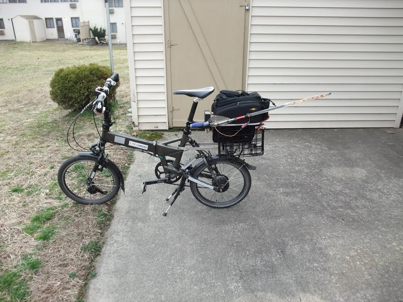
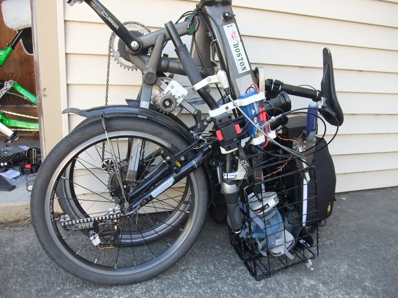
I'll go days - if I'm lucky weeks - without driving a car. My daily transportation is a 2010 Dahon Jetstream folding bike. The folding is key, as most places I go a folding bike is allowed on trains while standard bikes are banned during peak hours.

This is my second e-bike build, though in full disclosure - my first build is still far from complete.
DSCF2982.JPG


Specifications:
Stock Dahon Jetstream, with
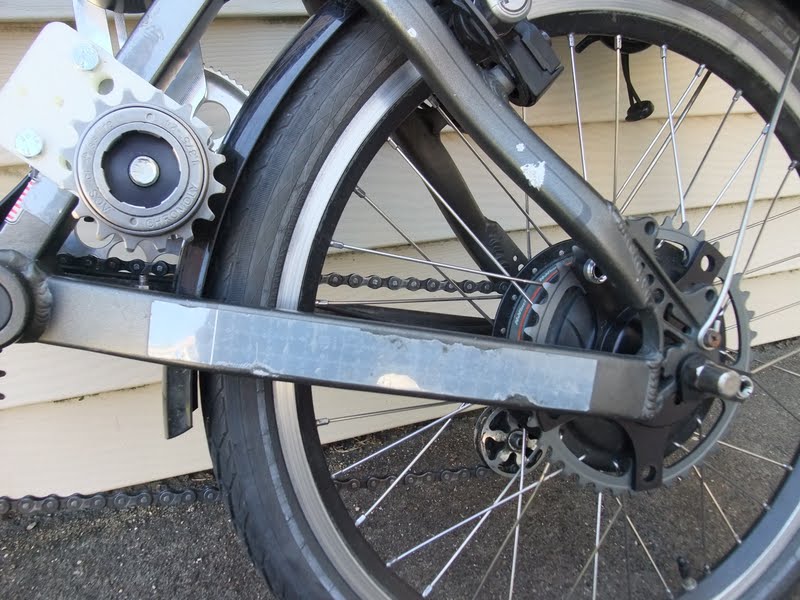
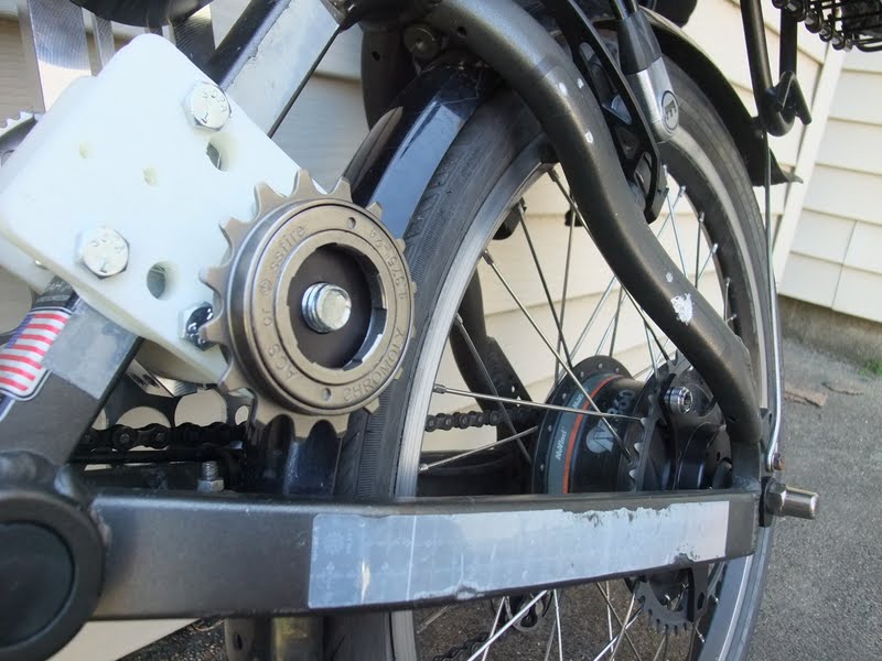
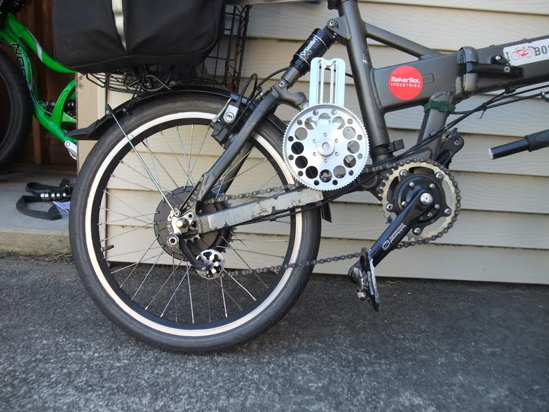
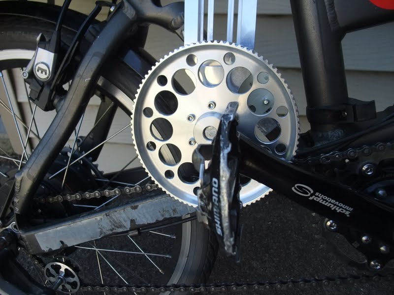
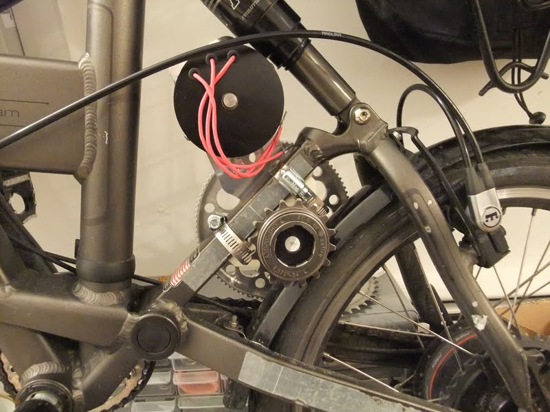
1) NuVinci N360 drive plus ATS Speed Drive - giving me a hell of a big gear range.
2) Decent carrying capacity - Topeak trunk bag, collapsable metal rack (fits a 12 pack of Harpoon IPA), and a mount in front that my back pack clips in to.

It's heavy with all the mods/crap, but I can still carry it up the two stories of stairs from the train platform to the street, which is something I cannot lose by going electric. That rules out a heavy rear hubby like the Cromotor.

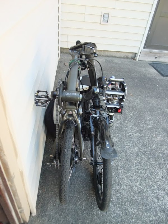
My challenge will be to add electric assist without losing foldability. Stealth would be nice but I'll settle for "plausible deniability". What I mean is, the bike is already freakish looking, and lots of people ask me if it's electric already (the big batteries I have strapped to the bike for lights, plus the NuVinci, it does look electric). I'd like to be able to keep electric assist low key so train conductors don't boot my ass off the rails...

More pics of this bike in my ATS Speed Drive install thread.


EDITS
19 Sep 2012: Changed post name from "The MENSTRUAL Cycle: Belt enclosure coming together"
25 Oct 2012: Changed post title to "The MENSTRUAL Cycle: Now with video"
--- skipped a few name changes
23 Feb 2013: The F3: Using a NuVinci on the Dahon JetStream
02 Apr 2013: The F3: Chain tensioners...
11 May 2013: The F3: Sharing the e-bike grin!
23 September 2013: The F3: Installing lights for the longer nights
03 October 2013: The F3: Maintenance!
07 December 2013: The F3: Close call, near wreck, preventable damage
21 February 2014: The F3: Keeping it going through the winter
11 April 2014: The F3: I've been blogged!
26 May 2014: The F3: I'm FREE... FREE-wheelin'!
26 Nov 2014: The F3: I'm on fire!
 
Current configuration:
I'm going to maintain and update the present day configuration of the bike here so it's easy to find.

Motor: Astro 3220, 5 turn

Drive components - guiding principles:
1. No smaller than 20t belt driver. I tried a 16t driver but it wore out in less than 1 year use.
2. Use odd number teeth, preferably prime number, for sprockets/freewheels/chainrings to make teeth wear more evenly.

Electric drive:
Performance - excellent. Very satisfying acceleration and top speed (speedo inop, top speed unknown)
Future upgrades: Consider 43 tooth chainring on second reduction, for parts standardization (same chainring as on human side drive).
CAv3 setting: . . . . . . . . . . . . . Throttle up-ramp: 0.05 X/yyy
Primary reduction: . . . . . . . . . 1:5 via 20 tooth driver to 100 tooth pulley
Secondary reduction: . . . . . . . 1:2.41 via 17 tooth freewheel to 41 tooth chainring
Total reduction: . . . . . . . . . . . 1:12.05

Human drive:
Known good combinations:
18t rear, 43t front
19t rear, 43t front works with a half-link

Performance - I recently changed the rear cog from 18t to 21t to get a better low end. This worked... too well, and I lost enough high end gearing to make the system uncomfortable at speed. I will tweak some more to get some of that high end range back at the cost of losing some granny. (An alternative would be to upgrade the ATS Speed Drive with a Schlumpf High Speed Drive, but that's very expensive.
Future changes: Consider changing the rear cog with a 19t for better ttop end human input.
Front chainring: 43t
Rear cog: 21t

Next up:
Running right now with the 43t/19t combination, but I don't want to use a half link in the long run. I might go back to the 43t/18t.
Using a chain length calculator (here: http://www.machinehead-software.co.uk/bike/chain_length/chainlengthcalc.html), it appears I can drop the half link if I use a 18t or 17t rear cog.
 
Electric drive:
This will be an RC build, I have an Astro 3210 and Recumpense V4 drive for e-power. It's a really really tight fit but I think I'm going to place it as shown below.
What you see is the V4 drive clamped to the vertical member of the rear suspension triangle. The clamp is a plastic mockup printed on a makerbot:
DSCF3185.JPG
With luck I can design a mount that will work here and with my other build; it's always cheaper to buy four of one design than two pairs of different ones.
 
OK, that pic above looks painful: The motor is in contact with the suspension triangle, the seat stay and the shock. This is the worst case scenario, and to get the pic I let all the air out of the shock. But, it's not bottomed. So I'll have to figure something out. Here's a closer look:
DSCF3190.JPG

I'll consider grinding some material out of the vertical member in the rear triangle. I don't think it supports as much stress as the other members. That, and I'll keep the pressure really high on that air shock. The suspension on this bike is to take the bite out of potholes, not for any serious off-loading.
 
I see why electric bikes is a hobby that brings out the passion. Everything is a compromise, strength, weight, price, location... Everything is at a premium. For my build, every millimeter counts. Here's a couple of shots of my e-drive chain line:
DSCF3186.JPG

Gonna need a chain tensioner to get the chain line on top of that lower chain stay...

I don't have a good shot of the alignment, but as it stands I need a shallower sprocket adapter, or I'll have a chain line that's off a few mms. I can't bring the freewheel closer to centerline without losing meat to clamp to. I can't bring the rear chainring out from centerline without the chain rubbing the upper chain stay. Stuck, in the middle.
DSCF3187.JPG


Here's the belt reduction on the right side of the bike. Note my neutered Norco A-Line hiding in the shadows to the left. Anyhow, the belt-drive fits in nicely between the arc of the cranks and the pedal-chain line
DSCF3194.JPG

DSCF3199.JPG
 
3mm is enough right?
DSCF3200.JPG


So much for stealth. Maybe I can have that belt pulley anodized black. Though I'm also considering making (commissioning actually) an enclosure for the belt drive, for visual and audio stealth and protecting the pants from high-speed running gear.
DSCF3202.JPG
 
Does it fold?

Yes.
DSCF3204.JPG


Is it really compact? No. But folded down as below gets me on Amtrak and commuter rail, and that's good enough. Also if I take the wheels and seat off, and ditch the panniers, it fits in a suitcase and can fly with me on commercial airlines.
DSCF3206.JPG

The location of the drive will not add any extra height or width to the fold, and more importantly won't interfere with the folding itself.
 
As my A-Line build drags on, it's now quite possible I'll have this bike done first. But progress here has been slow as well.

After some more thinking, I have a much better fitting drive system. Presently it's a custom mount piece printed on a MakerBot, attached with hose clamps, holding a Recumpense V4 drive. I also installed a shock that's an inch longer than stock.
DSCF3297.JPG


I'm going to ride it a couple of days with these parts attached and check out the dynamics of it. I've ridden that shock for a week over some harsh bumps - off a curb is the worst this bike sees - and I stayed more than an inch from bottoming. That's good because the motor won't clear if the shock bottoms.
 
OK, to improve my reduction ratio and live better within the room I have available for a chain line, I'm going to swap that freewheel you see above for a 13 tooth

Available from multiple sources probably, but at the very least from FFR Trikes:
13TOdyssey-2T.jpg


This freewheel has a smaller inner diameter than the 1 3/8 typical freewheel, so that means I'll have to get a freewheel adapter - this is harder to source, but also available from FFR
11SSMicro-2T.jpg


Edit: I originally wrote the below. And was completely wrong. I will not need to flip the freewheel or its adapter! :oops:
MattyCiii said:
It appears I can probably get away with mounting the freewheel "flipped" - so the grub screws are on the outside - which will place my threads and freewheel pawls working in the correct direction. To do this I'll need:
1) A longer shaft. Presently I'm using cheap soft nickel plated all thread to model everything and thus estimate the distance. Once I can get good measures I'll source a new shaft with the correct/longer length. It needs to be about an inch longer.
2) I'll need a custom spacer. See the top pic from my previous post. With the freewheel threaded on, about half of its depth sticks out from the depth of the adapter. This will need to be spaced at least 1-2mm away from the shaft collar. So, I'll need to find or cut a 1/2" ID by ~3/4" OD spacer just long enough to fill that gap. I'll take some pix to illustrate, next time.
 
Good work! I know nothing about RC drive, but I like it!!! That makerbot is certainly useful for making custom parts.
 
fractal said:
Good work! I know nothing about RC drive...
That makes two of us!


fractal said:
That makerbot is certainly useful for making custom parts.
When it works. I think I've got my last big problem licked though, so I'll be able to print out things I need. The ABS plastic pieces (think: the plastic used in LEGOs) is pretty strong, but certainly not up to the strength required by actual drive components. In this case it's a great way to prototype a custom mount to validate the design I will later make out of aluminum, machined by the likes of eMachineShop, bigbluesaw.com, or me and my scroll saw :?

ABS plastic mght be tough enough for items seeing less stress. For example I plan to print a mount for a chain tensioner on the 'Bot.
 
looks like crazy power for this small bike. i like it. it plays in the league of the e-moulton miles build.

I found this cheap foldable bike at the bay and would like electrify it with a 500W hub motor (quick and simple):

7950147SL20BSF01BL_T_1.jpg

I use bendable alloy sheets (Al Mg 3, 2.5 and 5mm thick) for my shaft mounts. It is also easy to weld and cut. And it is durable if the part is designed right.
The pieces which fit the frame can be made of plastic - I use 15mm thick PE plastic for it.
 
crossbreak said:
looks like crazy power for this small bike. i like it. it plays in the league of the e-moulton miles build.
You're too kind, I still have a long way to go before I can accept such a compliment! For now it's all just a bit of kinetic sculpture hose-clamped to a pedal-powered bike!

crossbreak said:
I found this cheap foldable bike at the bay and would like electrify it with a 500W hub motor (quick and simple):

7950147SL20BSF01BL_T_1.jpg

I use bendable alloy sheets (Al Mg 3, 2.5 and 5mm thick) for my shaft mounts. It is also easy to weld and cut. And it is durable if the part is designed right.
The pieces which fit the frame can be made of plastic - I use 15mm thick PE plastic for it.

Just be careful about axle width. I know with the Dahon, the front axle is narrower than standard. That said I suppose a "cheap" folder won't have too many custom parts, such as extra narrow hubs.
 
You are on o good way to gain this achievement, building a commuter with 1kw+ is beyond my horizon because I commute 30km+ every day with 350Watts and a 15ah 36V pack which is heavy enough.

But for commuting 15km and less your bike will be great fun! It does have this BMX stile cuteness along with power I'd love to drive

Everything what's above 500Watts continuous on the crank will kill cheep (shimano...) drive-trains within 3000km IMO
So I want to install a sachs 3-speed which will last about 1000Watts in total (300 Watts for me 500 for the motor) for a long time I guess.
Your Nuvinci would last much more but my 3spped hub was for free 8) The folding bike should have a rear axle width which fits my sachs drive (135mm).

Why don't you run the motor power through the NuVinvi?

Also have a look at bended alloy ... it's too easy, cheap and helpful to miss :shock:

just have look at my 2-stage headlight (for the motor mounts vistit my tongxin project) :
file.php

[attachment]
 

Attachments

  • headlight.jpg
    headlight.jpg
    237.9 KB · Views: 5,180
OK, a little bit of catching up.

My mini freewheel adapter and freewheel arrived. I selected the ACS Crossfire FWs instead of the Odyssey shown above; I already own the ACS removal tool, so I'm trying to standardize.

I've been riding the bike on and off with more and more of the drive mounted. I've ordered a longer shaft tube (cut to size by online metals.com). I needed an additional 6mm over what comes standard with the V4 drive. The shaft itself has flats to support flexibility in drive mount width - so I'm taking advantage of this and hopefully don't need a new shaft. Here you see it recessed into the FW adapter by that 6mm I need...
DSCF3303.JPG


With my current parts placement there's a great chain line, and I have about 4.5mm clearance for the large belt pulley on the left side of the bike. What makes the chain line possible is using 5mm chainring spacers, to offset the chainring toward the centerline of the wheel. First I tried a 60t chainring I had laying around... Not exactly stealth!
DSCF3298.JPG


The 60t is too big for a good chain line. Other practical matters, like putting air in the tires, suffers too. Next up: 53t. This one is black and has a bash guard.
DSCF3299.JPG


I finally got off my duff and installed the belt (not easy to see, it's on the other side). But this was crucial - if I can't get the motor to sit where I want it to with the belt on, I need to research, buy and wait for a new one. As it turns out the stock belt will likely work just fine! Here you see it with the shock just about bottomed. I let all the air out of the shock and use a come-along strap to sinch the shock down to minimum. See how the motor still has space.
DSCF3309.JPG


Here's the right side of the bike. Suddenly I have an overpowering desire to have the V4 drive parts anodized black!
DSCF3318.JPG
 
For protecting the motor against bottoming out the shock, you could install a limiter for the swingarm action. It could be as simple as a metal tube just above or below the motor that has one end against the opposite frame member from the swingarm, with a relatively thin plastic or rubber damper at each end, so that if it does bottom out it will not be *quite* such a WHAM.

It would probably be easiest to do this using the makerbot to make a stack of ABS sheets cut and shaped into a block that can go just below the motor, bolted either to the Recumpence drive plate or clamped to either the swingarm's front tube or the frame's seattube.

But I would personally want it to be where any load transfer goes into the places already beefed up to recieve it, like at the toptube/seattube junction where the shock already bolts to, or just under the motor to the seattube/maintube junction (assuming you can spread the force across that whole area of the seattube). I have crushed frames trying to invent suspension on them without first reinforcing the mounting points. :oops:
 
Thanks Amberwolf!
For now I will just keep the shock pressurized 20-30% higher than where I've been running it - where I know it won't bottom out.

I took the plunge tonight on ordering a custom mount. Initially it'll be hose-clamped to fix it to the frame, but I have through holes in case I later want to bolt it. This time I decided to go to Big Blue Saw - a water jetting house.

The price for 5 parts is the same for 1 (based on a small sampling of designs I've uploaded to them). As a result, I designed my mount to use two identical pieces, stacked - and had six cut. So I'll have enough spare parts to do 2 more bikes (Anyone selling a 2010 Dahon JetStream?). Here's what the mount looks like:
Dahon%2520mount.jpg


The bottom is not flat - Each side has a rise of 0.5mm as you go from center-bottom to the outside edge. When installing, one side is socked down tight with one hose clamp. The other side will thus have a slim pie shaped wedge divergence from the flat, from the center cut to the edge. The V4 drive shaft collar is slipped into the 35mm center circle. Then the other side is socked down via hose clamp. By the time it is flat/flush with the bike frame's square tube, the 35mm center should be exerting pressure from all sides onto the shaft collar. I hope!
 
Big Blue Saw has completed producing my mounts and submitted the package to UPS. Hope it arrives by mid next week... I'll be stalking brown box trucks until then :wink:
 
crossbreak said:
looks like crazy power for this small bike. i like it. it plays in the league of the e-moulton miles build.

I found this cheap foldable bike at the bay and would like electrify it with a 500W hub motor (quick and simple):

7950147SL20BSF01BL_T_1.jpg

I use bendable alloy sheets (Al Mg 3, 2.5 and 5mm thick) for my shaft mounts. It is also easy to weld and cut. And it is durable if the part is designed right.
The pieces which fit the frame can be made of plastic - I use 15mm thick PE plastic for it.
Two thoughts:
1) Not a lot of chain wrap on the pedal chainring. Maybe that can be solved with a chain tensioner between the motor and the pedal chainring. That will also give more chain wrap to the small motor sprocket
2) Unless the motor has really low KV, and is run with low voltage, you will need some reduction.
 
crossbreak said:
Why don't you run the motor power through the NuVinci?
I'd love to, and some day I might. But for now, it's all about reliability. Powering through the NuVinci would mean both human and e-power through one chain. Complex arrangement at the drive sprocket. Extra stress to NuVi freewheel and internals. Too much risk of something breaking

In contrast, putting e-power on the left means I have two fully independent power sources to get me home. If "one side" should fail, I can detach the chain on that side at the master link, throw it in the bag, and get home on the other power source, no sweat.
 
Thx for your answers.

1) Not a lot of chain wrap on the pedal chainring. Maybe that can be solved with a chain tensioner between the motor and the pedal chainring.

That would violate rule #1 for the build of chain drives: never put any chain tensioner into the tight span of a chain drive
I hope the chain wrap will be ok the way I designed it already. A normal bike sprocket of a shift drive does not get more chain wrap,too and it still works. A chain guide which prevents the chain from falling off would be a possible solution.
The chain wrap of the crank chain ring is a concern. I just hope it will work with the chain tensioner right behind the chain ring.

2) Unless the motor has really low KV, and is run with low voltage, you will need some reduction.
I want to use a 36 front driving Q128 hub motor with 200rpm @ 36Volts. It has a 1:8 planetary reduction, so the inrunner should runs @ 1600rpm max.
The hubmotor gets a 16T sprocket, the 3-speed hub a 15T, the crank chain ring will have 44 teeth. I wanna start the project next month when I have the money for the folding bike.

I'd love to, and some day I might. But for now, it's all about reliability. Powering through the NuVinci would mean both human and e-power through one chain. Complex arrangement at the drive sprocket. Extra stress to NuVi freewheel and internals. Too much risk of something breaking

In contrast, putting e-power on the left means I have two fully independent power sources to get me home. If "one side" should fail, I can detach the chain on that side at the master link, throw it in the bag, and get home on the other power source, no sweat.

I understand your concerns. But driving the power through the Nuvinci would gain you a hill climb ability improvement of 360% with the same top speed in theory :D
 
While I wait for parts (e.g., custom drive mount) I'm trying to get ahead of what I'll need next. Next up will be an enclosure for the belt drive. I'm enclosing it for the following reasons, in order of importance:
1) Protect me! I've placed the belt drive right next to shoe laces and pant legs. Though I tuck in the pants, there's still potential of me getting clothes in the spinning stuff and I don't want that
2) Stealth. The raw shiny aluminum is just too eye catching. The bike itself is distinctive, but I don't want to draw attention to it's e-bike nature.
3) Protect the drive. As a folding bike, there's high potential for parts to get banged up. As I type this the bike is laying on its side in the baggage space of a bus - things like this are beyond what a normal bike sees regularly and drive up the risk of damage. Gotta keep my e-drive running nice!
4) Reduce drive noise.

My plan right now is to get thin, rigid covers for the top and bottom of the drive pulleys, and print custom sides on the Makerbot. I only have 9mm total space, so things will be tight. I decided to go with 1.5mm thick carbon fiber panels from DragonPlate.com. CF should be strong and rigid. DragonPlate will custom cut panels, so I'm having them send me a quote. Below is a render of what will be the top piece:
Cover.jpg


It'll bolt to the Makerbot/ABS plastic all around, and to a custom piece between the pulleys/inside the belt line. Those ABS parts will bolt to the bottom piece, which will attach to the V4 drive.
 
Continued from above.

The cost of the carbon fiber/CNC cut service is much like anything else - relate do the types and number of cuts, and related to the stock material used as an input. My two covers will fit on a standard 12" x 12" CF panel. As I laid it all out during design, I noticed there was a nice ~4" chunk left over, so I designed a cover for the freewheel side of the drive system. Only the outer cover of this piece will be CF - and only because there's "extra". The rest of that cover system will be printed on the MakerBot.

Of course, much like everything else like a build like this, there's a lot of waiting involved. Indeed this not a hobby for impatient people!
 
a protective cover should be indeed as light and durable as possible. CF ist a good material for this if you laminate it on a 3D model from foam.
The same is possible with Fiberglass but a bit less expensive.

Waiting for parts is booring. I like to build them myself.

I always
-print out my parts,
-cut the paper with a scissor and then
- glue it onto my alloy sheet.
-I cut it with a drill at certain points to have starting point for my fret saw. Then
-I drill the mounting holes
- the I counterbore my mounting holes for the conic screw heads

Then I might bend the sheet if it is a AlMg3 alloy sheet.

But the fibreglass is the best solution IMO. I learned this from a local amputation appliance maker, but it's also good for covers
 
Back
Top