APL's DIY axial-flux motor

A variable magnetic fields induce a voltage in a conducting path 90° from his vector direction. So a rotating magnetic field induce a voltage in radial lamination. If the isolation is perfect no current is flowing, so all good, but in reality it isn't perfect so small currents are flowing and causing drag. The continuously wind stators (most axial flux motor are made that way) have not this problem since all lamination are tangential.
Maybe not accurate but that's how i see it !

Envoyé de mon Redmi Note 3 en utilisant Tapatalk

 
I'm not sure about the math concerning lamination direction, I haven't looked too closely at it since it's generally
understood to go in the direction of rotation. But then theres the Metglass wound cores, which beg to differ. So there
may or may not be more to understand there. They do have a slit in the core windings, to keep therm from being
a one turn short.

Google Images is my go to spot for searches, and theres tons of info on lamination theory, but much less on direction.
https://www.google.com/search?q=eddy+current+in+laminations&tbm=isch&ved=2ahUKEwjp6NCFgJvqAhUMTK0KHTD2CAMQ2-cCegQIABAA&oq=eddy+current+in+laminations&gs_lcp=CgNpbWcQDDoECCMQJzoHCCMQ6gIQJzoFCAAQgwE6AggAOgUIABCxAzoHCAAQsQMQQzoECAAQQzoGCAAQCBAeOgQIABAYULLbA1j43ARglvsEaAFwAHgBgAGnAogB3EGSAQYwLjYwLjKYAQCgAQGqAQtnd3Mtd2l6LWltZ7ABCg&sclient=img&ei=kZDzXqncLoyYtQWw7KMY&bih=1012&biw=1680&hl=en

The stator making machine has been shown here a ways back,.. this thread is getting so long in the tooth that I can't find
anything anymore. An amazing machine for sure, but as you say, not so DIY friendly. I don't think one could make a DIY
machine very easily, and lamination material hard to get get in small quantities as well.

I have seen 8" Metglass transformer cores for sale, and have often thought about cutting one up for cores, but didn't have
a way to do it. The water jet idea could change that though.
Might make a novel motor, but it's really kind of backwards to design motors around pre-existing core sizes. And tooth
shapes & brims become more difficult to create, if at all.

I guess I'm not sure how small of a core you can make for a certain motor diameter. The way I understand it is that you
start with the diameter, and tooth count, then determine coil span with the 150 degree formula, add the turn count wire
size,.. and whats left is the core face area.

if you want to make that size smaller, then the brim becomes longer, and the pole pitch, or PM magnetic hookup becomes
less, as Thecoco974 stated. So you might as well make a smaller motor? Maybe not, since theres still the advantage of
diameter.

To avoid saturation, I think you have the option of making the tooth longer.
 
I've been busy with the drudgery of winding the coils on this motor. (remember the motor?) It's been slow going. I had
to spend a lot of time finishing the core machining for the mounting screws and standoffs, so they could be mounted.
I should have let Coleasterling do it when they were made, but I wasn't quite sure about the dimensions then.

Anyway, should have something to show pretty soon. In the meantime, I was looking at the cores today, with the mounting
hole I drilled in the middle, and it stuck me,.. did I make a one turn short out of each core by putting a hole in them?
Hope not.
 
APL said:
...
To avoid saturation, I think you have the option of making the tooth longer.

APL,
Saturation starts limiting at higher flux density, in units of Tesla, which is equivalent to Webers per square meter. So it is the cross sectional area normal to the flux path. A longer tooth means increased magnetic path length which is counterproductive except perhaps providing room for additional turns (more copper).
Regards,
major
 
APL said:
Anyway, should have something to show pretty soon. In the meantime, I was looking at the cores today, with the mounting
hole I drilled in the middle, and it stuck me,.. did I make a one turn short out of each core by putting a hole in them?
Hope not.

It's been a long time since you made this decision indeed, but the smd material you choose has for first characteristic a low conductivity but a high magnetic permeability. Being non conductive no current can be induce by the rotating fields hence no one turn short !

Envoyé de mon Redmi Note 3 en utilisant Tapatalk


I see what you mean by the CSA major,.. so a shorter tooth is desirable. The minimum width or span to avoid saturation
is related to the max current intended, or Tesla's developed. A 1K motor could be narrower than a 2K motor. I'm not sure
how brim length ties in to that, but I've seen some really long ones.

Long brim axial tooth..png

I'll keep working on it,.. I know I can reduce the core width a little, because I have wire outside the brim at the moment.
If I go back to end turn brims, theres 10g's saved. About 20g's per core is probably all I could hope for, or 720g - 1.5 lbs
overall. Doesn't seem like a real game changer, but I guess we'll have to wait and see what this motor weighs in at in the end.

Sounds good Thecoco974, it's not completely non conductive, but I think you right. I'm still a little unclear on the whole
1T short thing, so I worry about having a repeat of the last motors problems, I thought I was out of those woods!
 
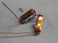
Not much to show for all the time I've spent on it, but I had a few false starts. Found some shorts because of the brim
edges, and had to go back and de-burr & rewind, and wrap some Kapton tape on all the cores.

Once I got started, I was wishing that I had used the 15 awg wire instead. The 14 awg is not staying completely under
the brims, and 20T doesn't conform very well, there should be 5 turns on the first layer and 4 turns on the next, etc,
so that the wire can stack right.

But I forced it all to fit anyway, and it's not 'too' bad. A millimeter or so of wire poking out the sides, and I think the
next round of coils will clear the first with a hair of room. I should have made the core centers a little narrower.
(Two unwound cores on top)

V2 stator progress..jpg

The next set of coils will have to be wound remotely, and then transferred to the stator, so I've got my fingers crossed
on that whole ordeal. I'll find out tomorrow. :wink:
 
I still think you should consider using thinner paralleled wires, that would make your life much easier and leave you more possibilities to experiment with. But nice job anyways, can't wait to see it finished
 
When winding the coils remotely, it might be good to put a little epoxy or Kapton tape on the outside to stick the wires together so it keeps it's shape when transferring to the stator.
 
It's my own fault Coleasterling, I should have known better. It's mostly the brim ends on the top and bottom. And I
should have used tape from the start anyway. Didn't show up on the first coil I did, so I thought it was good to go,
and I really thought that this 200C enamel was tough enough too.

I did the math, but reality begs to differ, the wire doesn't wind perfectly flat so it takes up a little more room on the
sides, and the two layers of tape take up some room too.

Coil clearance..jpg

Overall, it's going to work, and I still have the option of re-winding later. We'll stay on course in the interest of getting
this thing to spin!
I'm not even sure I can put enough power into it to justify 14 awg. yet, so that remains to be seen. The new battery
pack might be good for 1500 watts, but I'll have to wait and see what the reality is on that too, since they're not new.

I'll be using two 48v 15.6Ah packs in parallel. Each with a 35A BMS,.. so 70A. (supposedly)
 
APL said:
Overall, it's going to work, and I still have the option of re-winding later. We'll stay on course in the interest of getting
this thing to spin!
I'm not even sure I can put enough power into it to justify 14 awg. yet, so that remains to be seen. The new battery
pack might be good for 1500 watts, but I'll have to wait and see what the reality is on that too, since they're not new.

I'll be using two 48v 15.6Ah packs in parallel. Each with a 35A BMS,.. so 70A. (supposedly)

There should be no problem with such low power expectations... Just think about how much power we can throw on a basic QS motor without having it burning... I throw 500 + amps on my motor phases everyday and they are still fine with it 3 years after, I'm almost sure the copper I have in it is thinner than what you have in yours, so don't be shy!
 
Thanks, thats good to know,..guess I won't worry too much. I've been thinking of putting a temp sensor in the wires,
I might get more serious about that, just for the data if nothing else, and it would help to keep an eye on things.

Since I'm using 200C enamel, (392F), evidently it can take an awful lot of heat without braking down,.. I'm sure that
the copper itself can take much more.
I probably should be more worried about the controller than the motor.

I finally figured out that I could wrap a four inch long piece of Kapton tape over the top of the core and around the sides,
then wind the coil, and pull the tape back around over the top, to hold the wire in place. (ribbon might work better)
Once they're mounted, I can go back and cut it off. So looks like we're good for go. :thumb:

Taped coil sides..jpg
 
Nice. The enamel stuff looks great. It might make a bad smell the first time you get it really hot, but that goes away after a while.
 
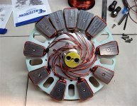
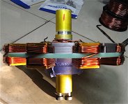
I finally got enough shop time to get the coils finished. Not an easy task,.. but done they are. Now it's time to face
the rats nest of wires in the middle.

But it will be joyful,.. because it's the last step before seeing it run. :thumb:

V2 coils wound..jpg

Bavaria winding diagram shows a pretty simple hook up, 3 coils together on each side, with the middle coil flipped, so
that should make things easy.

IMG_2336 (1) copy.jpg
 
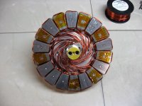
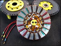
Yet another stator shot, I know,.. but this should be the last one. :wink:

The wiring cleaned up quite a bit once the wires all found they're place's. I cut some small copper tubing with a tube
cutter to make all the crimp & solder connectors, soldered in the phase wires, and she's all done! :thumb:

Stator finished..jpg

So it's time to put it all together at long last, and give it the juice. Barring some unforeseen disaster, the next post
should have some running specs. Time to put it in the bike,.. take it out on the road, and see what it will do. 8)

Still have to make the cooling fan segments, and finish the new battery pack project, before I can give it some real
power.
 
Looks professional done and for sure it will work well and powerful :thumb:

How is the airgap width?
Do you run it sensorless first?
Can you measure BEMF to see how good it will work with FOC and sine controller?
 
Yea, she's a hefty girl,.. I'll find out what the final weight is today. I'm thinking I might have created a bigger motor
than originally intended. :confused:

The air gap is close to 1mm, but I haven't put it together yet with all the cores in, so I might have to adjust that a bit.
Sensorless, yep. I like sensorless because it's simple,.. at least, for experimentals. I might go sensor later on, but I
don't mind a little noise,.. kind of like driving a stick vs an automatic.

Measuring BEMF is a bit of a mystery for me yet, do you have a recommended way to do it? I know we've talked about
scopes before, but still don't have one. The more I look into BEMF, seems like the more confused I get.https://pdfs.semanticscholar.org/e0e9/9963dca5063c4a958394f04be217fc428834.pdf
 
I was hoping for an easy assembly, but she's going to give me grief. Lots of little things, but the main snag is the air gap.

I thought I had it dialed in, but there was still some bearing room between the rotors, so it's down to shimming and
taking the motor apart several times. The pull power of all the magnets and cores together is unbelievable, and I had to
stop and make special pullers to get it apart again,.. for awhile there I didn't think I was going to be able to!

I found out that the stator isn't flat on the axle either,.. it's about .017" off on opposite sides, or .035" overall. Not much
by itself, but in a 1mm gap it is. Probably happened when I turned the glass board to get the cores to touch.
It's what we call a cascading mistake.

I think a better design would be an aluminum center ring, and just use glass board for the outer ring that holds the cores.

I did manage to weigh it once it was together though, and it came out to 17 lbs. So 11 lbs for the stator alone, and 6 lbs
for the rest of the motor. So thats another little set back, as I want it to be lighter than the 16 lb Crystalyte H35, but I
think the cores have a little to much iron in them yet, and I'm not going to cry over 1 lb.

Anyway, lots of futzing and shimming to do yet, but I'll get it.
 
1.5mm gap won’t be too bad if you need clearance. Rubbing is a show stopper.
I agree that an aluminum center hub would be nice for added stiffness.

I’ve seen a design somewhere that had an easily adjustable gap but I don’t remember how it worked. I’m sure it would be more complex to make and your shimming only needs to be done once (hopefully).
 
An aluminum center hub is not out of the picture yet, I think it could still be an option. I worry a little about the torque
strength of the current set up, but we'll see what happens. If I have to rebuild the carrier, then so be it. The cores and
wiring should come off in one piece, I just have to unsolder the phase wires and unscrew the cores.

The adjustable gap is an interesting idea. I can't do it on this motor because of the spacers, but I could maybe put a ring
of set screws in the bearing caps that push on the outer bearing housing. That would adjust the rotors left to right a little,
which would really help, and is the main pain right now. Something to think about.

The first motors original design had the back iron on the outside of the rotors, so the iron and magnets could be removed
and adjusted without taking the motor apart. A lofty idea, and not really possible with trapezoids.

I'll see what today brings,.. maybe I'll get lucky.
 
Nope,.. not lucky. :(

After three days of getting spanked, I think the culprit is a weak carrier. No matter how I space things, the
magnets are always smack up against the cores the same way. So I'm getting that old feeling.

I'm going to do a lateral strength test of the rotors and the stator separate, to be sure it's not the rotor assembly, but
I'm pretty sure it's the glass board carrier.

So that's another show stopper. But.. the show must go on, so what to do. :?: A quick fix would be nice, but I'm
thinking it might take a full reverse.

Even with a good solid aluminum center hub, theres a chance that the fiberglass board might not have the strength.
I guess that remains to be seen yet. I don't see too many other choices for materials.

So I still have some things to try on the motor yet,.. I could still be wrong about it. That would be nice...
 
Back
Top