APL's DIY axial-flux motor

Can you post a cross section diagram of the centre piece and core carrier? It looks like you could get a couple of dished reinforcing plates in there to limit the flex, might be tricky with all the connections but maybe easier than making a whole new carrier. Sorry to hear it's having issues, I'd have though that carrier would be plenty rigid enough but I guess it's easy to underestimate just how much force the magnets have.
 
Well that's bad news.
But there's something I'm not sure to understand: the stator is pulled towards the rotor plate by the magnet, but there are two rotor plates, one on each side. So in theory they should both cancel each other's effect, at least most part of it. So how come it doesn't? Did you entirely assemble the whole motor ?
I can see that happening with just one side being mounted, but not really with both sides and the spacers.... Could you post pictures of the assembly process so maybe we could help pointing out something?
 
-The attraction is going to cancel out nicely only when dead centered and that's never quite going to be the case, the force from the side that's a tiny bit closer will quickly dominate and it will get pulled in until contacting at a guess.
 
Bummer to be sure, but thats experimental, and inventing in general. Things don't necessarily show up until the end,
and then when it rains, it pours. Par for the course, just one more problem to solve.

The two rotors attraction is canceled out for the most part, I agree, but magnets and steel are always at war, and I
think thats where the forces are. (maybe?) Hmmm...

To be clear, the stator only touches on top and bottom, or two sides, and when I force the rotor to turn I can find a spot
that is 'almost' free of contact,.. so it may be that the carrier is not completely weak, but just needs some help.

I have to run some test to make sure that I'm not wrong about all this yet. It's really hard to figure out whats going on
with the motor all together. It still may be a crooked something, but I doubt it. I spun the stator separately,.. sideways,
on it's bearings, and it was less than .010" off anywhere. Not the 2mm thats showing up once it's together.

I'm hoping your right stan.distortion, there is the large washer that I put on the wiring side of the stator, to help reinforce
the fiberglass plate,.. mostly to keep the screws from crushing. I was going to bond them together, but decided to keep
the option of taking them apart.

Perhaps if I make another 6mm thick washer for the other side, and rivet the two together, sandwiching the glass board,
it would strengthen it enough? That would be 3/4" thick overall. and might tell us something, at the very least.

Otherwise, I can cut the center of the stator out. and make a 1/2" aluminum center hub that holds the fiberglass stator
ring. I'll have to do a drawing, and see if thats feasible yet.

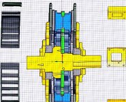
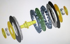
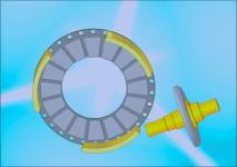
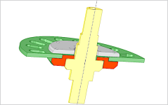
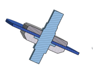
Definitely appreciate your help, and any suggestions,.. heres some graphics, if they help, but they don't show the 6mm
thick washer, which goes almost all the way to the cores on the right side.

(Cross section is a bit of a mess, but I've learned a lot since then.)
V2 crosection..jpg

Cad 2..jpg
 
Do you have some pics of where it's bending ? and how it looks ?
Glassfiber board if dense enough shouldn't be that much less stiff than Aluminum ( glass fibers have a young modulus of approximatly 72 GPa and 6060 aluminum 70 GPa, considering a 60% dense fiber board it should still be 45 GPa) Can you bend the stator by hand ? (precise enginering technique right here)
When mounted is it possible to pry the stator away from the rotor where it rubs to see if it can settle at the equilibrium point ?
 
Fibreglass... for something quick and dirty could you pot one side, maybe a paper ring around the inside and outside diameters and another around each coil so they can still be removed and pour in resin? Not nice but it should add a lot of stiffness. Was wondering if webs could be run between the coils but can't see any simple options that are also none magnetic.
 
toolman2 said:
-The attraction is going to cancel out nicely only when dead centered and that's never quite going to be the case, the force from the side that's a tiny bit closer will quickly dominate and it will get pulled in until contacting at a guess.

Yeah of course it wouldn't be cancelled entirely, but the resulting force of both opposing attractions combined should be much more manageable than just the one.
So provided it's not too far of being centered in the first place, it should in theory not see that much attraction difference. At least that should be valid for the motor just sitting there, adding current in its coils would definitely be another story.

@APL, could you post some pics of where it rubs exactly? there are several different ways to understand what you descibed, not sure which one it is.
 
I'm going to work on it today, and I'll take some pictures, but there might not be much that can be seen. I'll see how
they turn out.

The stator can be flexed by hand a 'little', and I'm going to try to pry the two sticking sides over the other way, and see
if it snaps to the other side. If it does, that would be proof positive that the carrier is the problem.

Another nagging fact is that the washer on the one side should stop the carrier from going in that direction at least,
which has got me scratching my head.

I tried prying on the rotor cage with a long bar and a pice of wood, to see how strong it was, and it didn't want to flex
very much at all. So I'm inclined to think that the rotors are alright,.. at least for the moment.

When I did the single coil test, the rotors spun straight, and the stator was centered, at least where that core pair was.
 
Another option, if need be, is to do it right and make the axle out of 4.5" round stock so that the axle flange is one
piece.

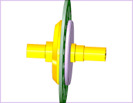
Wide axle flange..png

I thought I needed room for wiring on that side before, and a piece of round stock that big is more expensive, but
things are getting more serious now, so maybe.
 
Darn dial up.

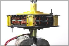
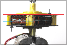
I finally got a good shot of the motor from the side, and you can see that theres definitely something wrong in
motortown. The stator appears tilted, but I also found out that the rotor assembly can be locked down in various
positions as well, which can cause an illusion.

Stator tilt..jpg

The rotors should not be able to be anything but straight, so that's another part of the problem, and another
reason why I'm having such a problem getting things centered.

I was able to get the adjustment good enough to at least turn the rotor though,.. still with rubbing, but at least
turning. So that tells me that it should have a chance at being strong enough with a little help.

Evidently the six small spacers I have are a bad design, and need to be extended into three long ones that use the
same bolt holes, with a few extra bolts in the middle. Or a single aluminum ring that goes all the way around,
like most axial's have.

The three piece spacers are budget friendly and I can make them here, but the 9.5" ring would be very expensive,
and have more cooling issues, so I guess three piece is the way to go first.

The current idea for the stator is to make a 1/2" thick aluminum washer, that I can press and bond onto the axle
flat, to give it some more strength. Then bolt the glass board in between the washers around the outer edge. :?:
If that don't do it, then it's going to need a new axle.

Spacers and support washer..png

The washer, at least, I can do right away,.. and may be enough to get the motor working.
 
Another idea is to make an adapter that fit's into a larger hole in the glass board, and bolts solidly down.

Axle addaptor..png
 
Is the misalignment caused by flexing of the fiberglass? Is it straight without the rotor in place?

The giant washer idea seems like it should work.
 
The fiberglass is straight without the rotors. I spun the assembly on it's bearings. By laying it on it's side and putting
two V-blocks under the bearings, it was less than .010" off anywhere side to side, using a dial indicator.

When the motor is together, and I pry the fiberglass the opposite direction on both sides at once, it doesn't want to
stay there at all. It seem's odd that it doesn't. I would think that if the fiberglass was the weak link, it should stick to
the magnets either way.

It doesn't even want to go there. It's acting like the stator is strong enough. But I could swear by looking at the picture
above that the stator is whats crooked.

When I put the whole motor in the lathe and spin it by hand, the outer surface of the rotor is off by .040", which is not
good, but doesn't seem to be enough to add up. It's only .020" per side.

Clearly, I need to beef the rotor spacers up with longer ones. I can't get anywhere unless the rotors are straight. I can't
even be sure that it's centered correctly yet because of that.
Reinforce the fiberglass just to make sure I have both basses covered. It's frustrating that I can't identify and isolate the
actual problem. :roll:

I was thinking last night that I should try setting the assembled motor's axle's on V blocks, and turning it, using a pointer
on the fiberglass ring, to see if it sways back and forth. That should help show whats going on.

Which washer idea do you like, first or second?
 
Yea, it's too bad, but to be expected actually. Same thing on the last motor. There's a lot of guesses work when
designing things, and the strength of the magnets is hard to figure. I was never sure about the fiberglass either.

Turns out that both the stator and the rotors are off by about the same amount. The old double whammy. No wonder
I'm having trouble. They are both bending towards each other. I spun the motor on it's axles and used a pointer.

I have a piece of aluminum flat bar on order, to make the rotor spacers out of, hopefully that will fix that problem.

I'm inclined to try the first aluminum washer idea first, because it leaves the fiberglass alone, and is fairly fast to do.
I think I might be able to drive some pins into the sides to help lock it in place too. Maybe.

I like the second version too. It's correct, and a solid fix. But I'm a little hesitant, because I'm not all that sure putting
a larger hole in the fiberglass is a good move yet, strength wise. Try the other way first because it doesn't ruin anything.

It may be that the fiberglass is not up to the job no matter what, in which case I need another idea for that. So, looking
ahead, just in case,.. carbon fiber is the only option for a replacement. There's also ceramic, but I don't see how I can
go that route at the moment.

Carbon fiber has resistance, so it's not perfect, and I don't know about cost yet, but should at least be strong enough.
One idea I had was to cut a small section out of the slots, and replace it by bonding in a piece of fiberglass. The two
composite's should bond well, and it would break the loop around the cores.
 
APL said:
The rotors should not be able to be anything but straight, so that's another part of the problem, and another
reason why I'm having such a problem getting things centered.

Evidently the six small spacers I have are a bad design, and need to be extended into three long ones that use the
same bolt holes, with a few extra bolts in the middle. Or a single aluminum ring that goes all the way around,
like most axial's have.

The three piece spacers are budget friendly and I can make them here, but the 9.5" ring would be very expensive,
and have more cooling issues, so I guess three piece is the way to go first.

I think those small spacers are the main reason for the problem.
It might help if you put spacer plates in the airgap during assemble just to keep its form during installation until all screws are tightened.

I hardly can believe that your stator plate would bend that much since the forces should balance out for the most part.
Is the stator 100% flat if you lay it down on flat surface (glass plate)?
 
Not sure if this would be accurate since it's possible that the picture doesn't make things look like they should, but the rotor seems relatively straight while the stator looks crooked...
asadfad.png

My vote would go to a combination of option 1 and option 2, using one big washer on each side while not changing the fiberglass inner diameter. You'll just have to rework a little bit your axle, but that would be really easy for you. Something like that:
ewtewrt.png

This way you can clamp the stator really hard on a lot of surface, so it should bend much less and remain strong.
 
The stator plate is flat, and it is bending, unfortunately. But it doesn't appear to want to bend any further. The rotors
are moving the rest of the way.

I would think that there would be an equilibrium too, and I'm thinking it will be more so during operation, when the
steel cores become opposing magnets, and not just steel.

I did use spacers during assembly, (popsicle sticks), but as soon as you pull them out,.. it snaps over. A sound I've grown
to hate!

I used to think that being able to adjust the air gap in an axial motor was a great feature, but now I'm thinking it's a
almost a curse. If theres any slop in the bearings, caps, or rotors, then there will be trouble. And the stator carrier has
to be very strong. Lessons learned.

I've got my fingers crossed, hoping that it's not the two piece rotors that are adding to the problem as well. But I think
that if it is, then I can re-assemble them with glue. Hind sight is 20/20, as the saying goes.

I don't think the photo can be used that way Dui, ni shuo de dui, although it certainly looks that way. Your combination
option looks pretty good though, and I hadn't thought of that. Theres not much room behind there, but there might be
enough. I'll have to draw it up and see how things fit. Good job.:thumb:

I can't make the washer thicker on top because of the wiring, unfortunately, I wish I could, but things are pretty tight on
that side.

I looked up carbon fiber plate, and see that 5mm is the common thickness. If I bond some .020" fiberglass to each side,
then it would make the thickness I need, and insulate the other parts, as well as strengthen the slot cuts. Cost...$50.

Carbon fiber is subject to eddy currents, but less than aluminum, (I think), and I was using aluminum on the last motor,
and I was using two plates. The motor ran fine, and didn't get all that hot, but I don't know how much of the heat was
aluminum related.

If it comes down to it, I could make the carrier out of 'all aluminum' again,.. cut and bond the slots, and make it thicker
where needed. One piece. It would be cheaper, and at least get things moving again. Just a thought.
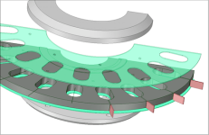
Carbon fiber carrier..png
 
I'd suggest trying the giant washer. You could use lots of screws around the outside edge to support the fiberglass. I think it would be nearly as stiff as having washers on both sides. Getting the screws in might be a pain with the wires in the way but hopefully they would bend enough to get them in. Really good epoxy might be as good as screws but I would still use some screws.

Going for a slightly larger gap will help the bending problem at the expense of some torque density.
 
APL said:
<snip>
(Cross section is a bit of a mess, but I've learned a lot since then.)
file.php

V2 crosection..jpg

Hi APL,
Too bad you're having difficulty. Often one pays close attention to the electromagnetic assembly overlooking basic machine design. I've been studying that cross sectional layout of yours. Can't say as I've ever seen where bearing outer races are not completely covered by the housing. Also the rotor sides and outer structure are comprised of multiple members and fasteners which could compromise stiffness.
I don't have design experience in "pancake" dynamos and could not find (Google) bearing layout design information on similar machine shapes. But I suggest you take a close look at what you're dealing with. I'll give a link to an article I did run across which speaks about bearing axial stiffness and tilt stiffness. Aspects I've never had to deal with but may come into play here.
https://www.sciencedirect.com/topics/engineering/bearing-arrangement
I'd like to see it run.
major
 
Thanks for the bearing info major, it's something that I hadn't really considered too much. I always figured that there was
a magnetic balance. I probably am using the wrong type of bearings. Should be tapered roller bearings, since more of the
force is showing up as axial.

I'll have to look it up and see if I can find some replacements. These are oversize bearings, and will probably work for a
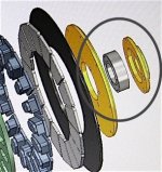
time,.. but not correct. The bearing caps have a relief for the bearings to sit in, so that they are covered a bit more than
the cross section shows. I would say that they are 3/4 covered, with about an 1/8" sticking out.

Rotor and cap..jpg

Your right about the multi piece rotors too, Another bad move on my part... trying to save a little weight. But I'm not sure
that it's a problem yet,.. there may be hope that I'll squeak by this time, but I won't do it again.

They're to thin too. they should be at least 3/16" thick, if not a full 1/4", and solid steel all the way to the bearing.
This motor has gotten a lot bigger than originally intended. (I've got runaway kilowatt. :))

But if I should have the cores machined back a bit, and use a little smaller wire, I think it would be a more balanced design.
 
You're bearing choice isnt' Bad, forces are going to be radial (chain tension) and no axial forces as they should be an equilibrium through the spacers, one bearing should no be all the way one his shoulder for this to happen without loading the bearing.
The stator must be stiff enough to resist only one half of the stator without snapping over. Beaffing it up is the way to go i suppose.

Envoyé de mon Redmi Note 3 en utilisant Tapatalk

 
Ya, no tapered roller bearings unless you are seeing much, much higher combined loading. A pair of deep groove ball bearings is ideal for this situation. One thing to be aware of is that you need to preload the set to remove any slop. Did you calculate preload and shim the bearings any? I don't remember how it is done in the emrax, but I don't think you'd want a spring washer shim for an axial-flux motor.
 
APL said:
I probably am using the wrong type of bearings. Should be tapered roller bearings, since more of the force is showing up as axial.
Deep groove is fine. You could probably look into using C1 clearance bearings (tight) if you need some additional stiffness. Shimming for a very small amount of axial preload would also help with stiffness of the assembly.
 
Back
Top