Dual rotor axial flux motor design

fechter said:
If the wire passes through the slot, it will be 1/2 turn, negating 1/2 turn of the strip. Running it the other way will add 1/2 turn, which would probably be better but you have to be sure it won't fight the BEMF from the other windings.
Thanks Richard. That's what I was thinking. Feeding it through on the other side, the current will be running in the corresponding direction for the adjacent coil, too (AaA, BbB etc..) . I'm worried that, with only 4 turns per slot, an extra 1/2 turn is a relatively large difference...

Making the connection on the outside to maintain an even turns count would be the best bet.
But, on the other hand, connecting the modules on the outside increases the overall diameter [and one of the reasons for exposing the endturns through the case was to maximise the mean airgap radius...], it also increases the length of the links between the phase groups.

Hmmmm........
 
Surely if you spun the windings 180 degrees around the laminations, you would not be adding any turns while having the connections on the outside of the motor...? Or am I missing something?

Chris
 
Hi Chris,
iti_uk said:
Surely if you spun the windings 180 degrees around the laminations, you would not be adding any turns while having the connections on the outside of the motor...?
Indeed.

Making the connection on the outside to maintain an even turns count would be the best bet.
But, on the other hand, connecting the modules on the outside increases the overall diameter [and one of the reasons for exposing the endturns through the case was to maximise the mean airgap radius...], it also increases the length of the links between the phase groups.

Hmmmm........

Miles said:
Ok. I'll model the "Pompidou" version, to see what possibilities it has.... :)
Or am I missing something?
 
I'm still trying to grasp what happens if the turn count is a little uneven. Since each phase is a bunch of windings in series, as long as the phases are equal, it may not make much difference if one winding has an extra half turn.

The current in a series circuit is equal everywhere, but the half turn difference will result in a tiny bit of extra torque on the core with the extra turn. Since the rotors are solid, the torque from each core adds to the total, so a slight imbalance should not do anything bad.

If there was an imbalance between phases, that would be bad, as one could slightly fight the other and cause a major efficiency loss.
 
I was worried that it might be a cause of vibration in the rotors.

How about making the connection along the length of the first half turn (from the edge)? You'd end up with a compromised start but it would be better than nothing?
 
I don't think the imbalance will cause a significant vibration in the rotors. The rotors are pretty stiff and the forces from normal running would be much greater than the imbalance force.

I'm not picturing your last idea.
 
Accepting some imbalance, I'm leaning towards increasing the number of turns from 4 to 6 and missing out the first half turn from the first module of each phase. Might as well gain the advantage of losing an endturn, too :D

Reasonable compromise?
 
I've just read this paper, properly - rather than skimming through in my usual fashion. It was fascinating because it deals with optimizing the same parameters that we've been working with in this thread.
 
Miles said:
Something like this. I doubt if it has any advantage over simply missing out the first half turn?

Magnetically there would be no advantage. If it makes building easier or gives the desired form factor, it may be OK.

That paper had a lot of calculus. I skiped that part, as it's just used for the model. I found the FMEA diagrams interesting. Looks like the back iron is close to saturation near the gaps in the magnets. Good to see the teeth aren't the limiting factor.
 
I think we may have passed you by on an axial flux motor.
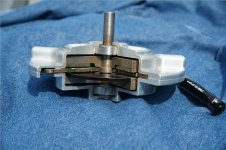
The photo is a cut out of the 1hp prototype. one of the two maganets and a slice of the pc board ''windings'', which are not windings at all can be seen.
The pc board stays put and the two maganet plates rotate on the shaft. Maganet plate is neo pie shaped encapsulated in plastic and bonded to the only matalic part in the motor that serves as return of the flux lines and is what is attached to the shaft.
This thing <2lbs., has no latteral loading, Flux lines weave back and forth, the windings are a printed circuit board, there is nearly NO back emf ( so we use very inexpensive audio grade componets in the controller). No cogging, no noise, no heat and is less expensive to manufacture than any motor ever built.
That's a uniball pen next to the motor, which is 3.250 dia. and little less than 2.00 H.
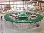
For stark contrast, second photo is 3MW of the same thing and in production to replace gearboxes and crap that breaks all the time on large wind turbines. Notice the guy walking past the assembly on the left.
core small.jpg

3mw.jpg
 
Any rpm
We can optimise specific rpm and torques by varying the gap between winding and maganet rotors, winding density and the such. Now moving on to a newer and more efficient winding board. Run some fea and you see what happens with flat printed windings and what to do to fix.
 
plasmadust said:
Any rpm
We can optimise specific rpm and torques by varying the gap between winding and maganet rotors, winding density and the such. Now moving on to a newer and more efficient winding board. Run some fea and you see what happens with flat printed windings and what to do to fix.

You wouldn't happen to work for these guys?
http://www.boulderwindpower.com/the-bwp-generator/pcb-stator/
I think the motors are so efficient they can use low temp grade neo out of California (no dysprosium need)
 
plasmadust said:
I think we may have passed you by on an axial flux motor.
The photo is a cut out of the 1hp prototype. one of the two maganets and a slice of the pc board ''windings'', which are not windings at all can be seen.
The pc board stays put and the two maganet plates rotate on the shaft. Maganet plate is neo pie shaped encapsulated in plastic and bonded to the only matalic part in the motor that serves as return of the flux lines and is what is attached to the shaft.
This thing <2lbs., has no latteral loading, Flux lines weave back and forth, the windings are a printed circuit board, there is nearly NO back emf ( so we use very inexpensive audio grade componets in the controller). No cogging, no noise, no heat and is less expensive to manufacture than any motor ever built.
That's a uniball pen next to the motor, which is 3.250 dia. and little less than 2.00 H.
For stark contrast, second photo is 3MW of the same thing and in production to replace gearboxes and crap that breaks all the time on large wind turbines. Notice the guy walking past the assembly on the left.

That's pretty cool. What is the thin disk below the windings?

And... how is Luke going to fit that 3MW one on his bike? :mrgreen:
 
Just came across this:

Design of an Integrated Starter-Alternator for a Series Hybrid Electric Vehicle:
A Case Study in Axial Flux Permanent Magnet Machine Design.

Jessica L. Colton University of Nebraska
 

Attachments

  • Nebraska.pdf
    1.8 MB · Views: 277
Miles said:
rhitee05 said:
Miles said:
Magnet shape modified to give a more equal flux density across the laminations.
This actually won't matter. I can't demonstrate this without full 3D modeling, but the flux won't be limited to just the narrow lower section of the core - it will spread across the entire volume of the core, so any worry about the narrow section of the core saturating first are mostly unnecessary.
I guess I just assumed that it would stay separated because of the reluctance of the inter-laminar insulation. Or, do you mean that it spreads across only as each lamination approaches saturation?
Ref: http://www.endless-sphere.com/forums/viewtopic.php?p=557247#p557247

As I'm milling pockets for the magnets anyway, I could increase the airgap distance towards the inner radius by milling the pocket at a slight slope. Good idea? Magnets tapered in thickness would probably be too expensive....

I'm still not sure how much the minimal lateral flux flow will increase as saturation of the narrower lams is approached?

file.php
 
The thin disc is one of two maganets.
One above and one below the winding pcb. the pie slice taken out of the entire upper maganet and Fe rotor for ease of viewing the assembly. The same pie slice is taken out of the winding pcb and lower Fe rotor, but maganet disc is intact.
The resolution of rotation is about 0.3 arc deg. and the orintation of the upper and lower maganet plates are so as to have + on one and - on the other giving the wrap of the flux lines a path off one thru the FE rotor and retuning in phase to the other. Hence the lack of heat generated.
It is a 3 phase brushless motor by any definition, but effeciencies are as good or better that AC induction.
We have made this and it is in production at Core Outdoor Power.
www.coreoutdoorpower.com for a better view than a cut up proto type.
 
flathill said:
plasmadust said:
Any rpm
We can optimise specific rpm and torques by varying the gap between winding and maganet rotors, winding density and the such. Now moving on to a newer and more efficient winding board. Run some fea and you see what happens with flat printed windings and what to do to fix.

You wouldn't happen to work for these guys?
http://www.boulderwindpower.com/the-bwp-generator/pcb-stator/
I think the motors are so efficient they can use low temp grade neo out of California (no dysprosium need)

http://www.boulderwindpower.com/about-us/board-of-directors/matt-jore/
"Prior to founding Core Motion, Matt was founder, CEO and Chairman of Jore Corporation, an innovative power tool product company based in Ronan, Montana. Under his leadership Jore Corporation grew from a start up to a publicly traded company with more than $50 million in annual revenues and partnerships with major OEM power tool multinationals including Makita, Black & Decker/DeWalt and Bosch. "

I see you lost control of your last business to the banksters. What a comeback story! Best of luck with you new venture!
 
plasmadust said:
We have made this and it is in production at Core Outdoor Power.
http://www.coreoutdoorpower.com for a better view than a cut up proto type.

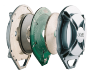
Here's the picture:
400-Exploded-View_horizontal-300x241.png
 
Back
Top