Dual rotor axial flux motor design

Still wondering if there would be a significant advantage in using grain-oriented steel (up to 30% higher flux density but usually has a lower silicon content than non-oriented)?

Electrical steel references:

http://www.protolam.com/page3.html
 

Attachments

  • Mag_Cores_Data_Bulletin.pdf
    300.1 KB · Views: 478
  • SMMA_Fall_Constantinides_081017.pdf
    1.7 MB · Views: 68
Good stuff. Thanks for posting this

Most of the common electrical steels seems to be characterized at only 50-60Hz. In Sweden there is a plant making good electrical steel. Some if their steels (like NOxx) are characterized to 10kHz.

http://www.sura.se/Sura/hp_products.nsf/vOpendocument/03A8B2433FAE16C4C1256AA8002280E6
http://www.sura.se/
 
Miles:
Still wondering if there would be a significant advantage in using grain-oriented steel (up to 30% higher flux density but usually has a lower silicon content than non-oriented)?

I would like that answer from thouse in the know also.....I also have found sourcing reasonable amounts of any of the ellectrical steels has been problematic for me. especialy in a finer thickness like .2mm (.008") the prototype lam houses require a reasonable amount up front (1st born or just your imortal soul) & have no interest in supplying a small qty of material to a model maker.

I did buy a couple rolls of cheap 1080 low carbon steel shim stock in .008"t to try my hand at photo chemical machining. We'll go into more about that somewhere else.

I need to read through the PDF's you liked in a bit more detail when time permits.
 
i dont see a point why not to make laminations : use 0.35mm or 0.2 mm soft silicone steel No. 250#.
winding wire perhaps : type(at least): Enameled wire, No. 2UEW, grade: F, internal resistance: 0.0087Ω
 
markobetti said:
i dont see a point why not to make laminations : use 0.35mm or 0.2 mm soft silicone steel No. 250#.
winding wire perhaps : type(at least): Enameled wire, No. 2UEW, grade: F, internal resistance: 0.0087Ω
I don't either Marko.

The idea here is to explore all the options. With most motor cores, it's not possible to take advantage of oriented steel. Here we have a segmented core with pretty much unidirectional flux paths. Is it worth trying oriented steel? I want to find out. It would also be pretty straightforward to use strip coils for the windings. Why not try that? It looks to give a significant advantage in fill factor.

Thanks for the link!
 
The thinnest Kapton tape is 64 micron of which 25 microns is the adhesive layer (40%!).

The technique used here looks interesting. Only 25 microns for the insulation! Pity that they only do it up to .005" copper thickness as a stock item :(

0.5mm copper thickness with the 0.025mm insulation thickness could give a fill factor of 0.8 :D
 
This is where I am, at the moment.

There is a 1mm recess in the can which restrains the core modules in the axial direction. The collective wedging action against the core spacer strips (green) force the modules radially outwards, into the recess. I'm relying on the integrity of the lamination bonding and compression from the winding. I could also wind a layer of Kevlar yarn around the inner section of the core modules before epoxying them.

Will this be enough??? :|

The coils will now be linked on the inside with circa 12 gauge wire, to avoid impeding the air flow.
 

Attachments

  • Wedge-core-retaining-system.jpg
    Wedge-core-retaining-system.jpg
    94.8 KB · Views: 1,660
Maybe something like an acrylic ring around the inner edge of the cores to keep them seated into the recesses?

If I understand the structure correctly, all of the torque reaction force is applied to those 1mm lips in which the cores sit? I'm not a materials or an ME guy, but that doesn't seem like a lot. On the other hand, this looks like a good arrangement to provide airflow over the coils and keep metal bits out of the magnetic path to avoid eddy losses.
 
The extended ends of the top sections of the core modules are shaped to the radius of the bottom of the recess. They could be bonded in but, I would have thought that the collective wedging action outwards, into the recess, would take a lot of torque to overcome? Reaction torque is going to be in the order 10 Nm, maximum.

Here's a different view:
 

Attachments

  • Section-view-2.jpg
    Section-view-2.jpg
    73.5 KB · Views: 1,610
What info would you need to do a FEMM analysis, Eric?

I could do a linearised section around the mid radius of the stator?

As this thing is going to weigh around 1kg, I need to know whether I'm likely to be able to get more than 4Nm out of it, continuously.... :)

Ref: http://www.endless-sphere.com/forums/viewtopic.php?f=30&t=14484
Miles said:
Goal:

- Over 4Nm continuous torque per kg of motor weight.

Rules:

- Less than 3kg in weight.

- No energy input other than that to the motor itself.

- Capable of practical use on an electric bike.
 
Miles said:
They could be bonded in but, I would have thought that the collective wedging action outwards, into the recess, would take a lot of torque to overcome?

You're the mechanical guy here, I'll definitely take your word for it. Just was curious.

Miles said:
What info would you need to do a FEMM analysis, Eric?

I could do a linearised section around the mid radius of the stator?

That's exactly what I'd need. Material specifications are helpful too if you know them - grade of electrical steel and grade of magnets - but I can make some assumptions otherwise. The grade of steel shouldn't make such a huge difference in the torque calculation, as I think the saturation curves are pretty similar. Grade of magnet is obviously important, but it's just a scaling factor. I can assume N40 unless you're planning otherwise.
 
If you angled the magnets/laminations you would have one of these:

http://www.novatorque.com/technology/conical-gap-geometry.html

As Luke says:
"The goal for any motor is to have as much active flux area (diameter and length) as you can fit in a given motor size constraint with out compromising the magnetics path (this doesnt mean the gap distance from tooth to magnet should be large, just flux area). It is never a bad thing to have more flux area, as it means to create a given torque, you can have lower flux intensities, and it carries ZERO penalty."

I think conical may have an advantage here, also allows them to use low cost ceramic mags, but now imagine this this design with neo or smco...or inverted
 
This is what the linearised section of half the mid-radius circumference looks like:

Shall I post it as a 2D DXF file?
 

Attachments

  • Linearised-stator-section.jpg
    Linearised-stator-section.jpg
    31.4 KB · Views: 1,646
flathill said:
If you angled the magnets/laminations you would have one of these:

http://www.novatorque.com/technology/conical-gap-geometry.html

I think conical may have an advantage here, also allows them to use low cost ceramic mags, but now imagine this this design with neo or smco...or inverted
It's an interesting design.. and avoids some of the structural problems of the axial flux topology.
 
Miles said:
Shall I post it as a 2D DXF file?

DXF would be very handy as I can import it directly into FEMM. How many slots/poles does the design currently have?
 
I've saved it as an A'CAD 14 DXF

Magnets to be N48

Air gap circa 0.7 mm

Allowing for insulation, copper fill ratio is 0.75 of marked area.

Possibly 2 x 6 turn coils (12t) ? This gives slightly under 0.5mm thick strip.

Magnet flux backing 2mm thick steel.
 

Attachments

  • Miles-linear-section.jpg
    Miles-linear-section.jpg
    21.7 KB · Views: 1,569
  • Miles linear section.zip
    11.5 KB · Views: 22
Got it imported okay. I'll simulate to be sure, but I suspect you'll probably want to make the magnet backing something like 3.5 or 4 mm steel, otherwise it may saturate before the core steel does. I'll start simulating with 2mm and see if it saturates and thicker is necessary. What's the core height (outer - inner radius)? I need to put that in FEMM to make the force calculation accurate.
 
Yes. I was going to start with just basic low-carbon 1006 steel, but I can change it if you have something else in mind.
 
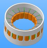
Not an expert in this area, but my limited reading suggests that low-carbon steel or pure iron is probably the best material for the flux ring. Outside of really exotic nickel alloys, pure iron has the highest saturation flux density. Silicon steels actually have lower saturation density, but higher resistivity (for eddy currents) and lower hysteresis. Since the flux ring is a mostly static field, you'd really rather have the high saturation. This reading seems to agree with the thread you linked.

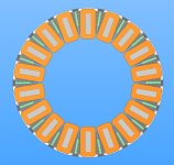
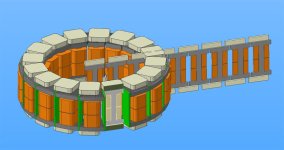
Also, I'm setting up the simulation using a AaABbBCcC winding pattern, per:
http://translate.google.com/translate?hl=en&sl=de&tl=en&u=http://www.powercroco.de/
for the 18 slot, 16 pole configuration.

It'll take me a little time to set this up and inevitably some debugging, but I think I figured out recently how to call FEMM from within MATLAB. This would have the same effect as using the Lua script within FEMM, except that I know MATLAB and not Lua! :) In any case, I should be able to use that to get the BEMF waveform and extrapolate Kv.

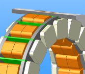
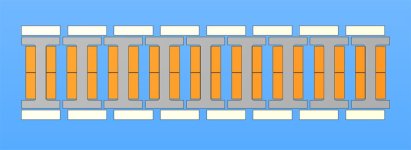
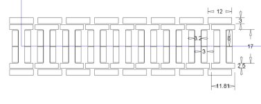
When you get a chance, is it possible to also get a linearized section at the inner and outer radii as well? I think I can so some interpolation between the different sections to try and estimate the effects of the wedge vs. square cross sections. It won't be as accurate as a full-3D solver, but should get at least some estimate of the effects. Actually, the best thing for this would be linearized sections at 1/6 and 5/6 distance from inner-to-outer radius. That will give me center cuts for each third of the radius.
 
Back
Top