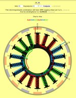
Dual rotor axial flux motor design

rhitee05 said:
When you get a chance, is it possible to also get a linearized section at the inner and outer radii as well? I think I can so some interpolation between the different sections to try and estimate the effects of the wedge vs. square cross sections. It won't be as accurate as a full-3D solver, but should get at least some estimate of the effects. Actually, the best thing for this would be linearized sections at 1/6 and 5/6 distance from inner-to-outer radius. That will give me center cuts for each third of the radius.
Ok, I'll do the 1/6 and 5/6 sections.

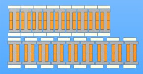
My naive reasoning was that, with a uniform inner core section and maximised end areas, square magnets (non wedge) would mean that no lamination of the inner core would be at greater risk of saturation than any other. The amount of steel in the ends of the cores is obviously a compromise for structural reasons.

I'm interested to play with the volume ratios of copper to iron in the main part of the core.
 
bigmoose said:
Reducing the number of magnet poles Nm. Hysteresis losses are directly proportional to the fundamental electrical frequency. Eddy current losses are directly proportional to the square of the fundamental electrical frequency. Since the fundamental electrical frequency is Nm/2 times greater than the motor shaft speed, reducing the magnet pole count allows one to reduce core losses significantly without lowering the motor shaft speed.
Does this mean that it's actually better to go for the lower number of poles closest to the number of slots (16 rather than 20, in my case)????
 
the more I learn....the dumber I feel.
All good questions Miles.

I suspect the answers are allways a variable......refined by paramertes yet to be named.
my current "challange" motor is looking like 24t & 10 pole prs (20mags)
for the reasons moose aludes to...although I back-doored into it, not really grasping the depth of theory.....more of a lucky or ironic coincedence. but i feel confirmed somehow :lol:
 
I think there are probably advantages either way. BM is correct that for 16p, the electrical/mechanical RPMs are a 8:1 ratio, for 20p they would be 10:1, so you'll get more hysteresis cycles per revolution using 20p. But, going over to the topic of Thud's thread, the calculator shows that 16p has 144 cogging steps while 20p has 180, so 20p will probably have somewhat lesser cogging force.

I'm inclined to think that it's a matter of application. 16p is probably more suited to a high-RPM motor, 20p for a lower-RPM one, although I don't think the differences would be all that dramatic.

When I get the simulation up and running, I think I should be able to at least estimate cogging force, although it won't be exact for the 2D model.
 
Another thing I need to do is review how Kv is defined in terms of the EMF waveforms. I think the simple definition is:

Kv = Vpp/2/RPM

Assuming trapezoidal BEMF. The definition is slightly different for a sinusoidal motor, although I'm pretty sure this design will end up with a more trapezoidal BEMF.
 
rhitee05 said:
But, going over to the topic of Thud's thread, the calculator shows that 16p has 144 cogging steps while 20p has 180, so 20p will probably have somewhat lesser cogging force.
But the number of cogging steps per revolution won't directly affect the total parasitic torque (and therefore efficiency)? Right?
 
rhitee05 said:
Assuming trapezoidal BEMF. The definition is slightly different for a sinusoidal motor, although I'm pretty sure this design will end up with a more trapezoidal BEMF.
At some stage, I thought it might be interesting to try round magnets, in order to get a more sinusoidal BEMF.
 
I believe it was stated earlier in this thread that this design wouldn't have any end turn losses. Is that true?

In a normal radial "outrunner" design, only the part of the windings that are parallel to the magnets will contribute to torque, correct? won't the same apply to this design?
 
bearing said:
I believe it was stated earlier in this thread that this design wouldn't have any end turn losses. Is that true?
I certainly didn't intend to imply that. :)

bearing said:
In a normal radial "outrunner" design, only the part of the windings that are parallel to the magnets will contribute to torque, correct? won't the same apply to this design?
Yes, in this case, only when the coils are running radially will they contribute to torque. If you have a wedge shape inner core (mine is uniform), you can take advantage of wedge shaped magnets but the proportion of the coils which is non-contributory will increase significantly. It would be interesting to do the comparison.
 
Deciding the ratio of iron to copper:

If the goal is to maximise the continuous torque output, the amount of iron only needs to be sufficient to avoid saturation up to that specific torque level. By reducing the amount of iron and so being able increase the amount of copper, you decrease both parasitic and direct losses and raise the maximum sustainable torque level by sacrificing the peak levels of torque.

So, working back from the maximum heat that the design can dissipate.........

Does this make sense, as a strategy?
 
Miles said:
But the number of cogging steps per revolution won't directly affect the total parasitic torque (and therefore efficiency)? Right?

Yes, the parasitic eddy current losses are separate from cogging. Cogging is an annoyance at low speeds, but is not a net loss to efficiency. The eddy losses will be proportional to the number of poles and the RPM, as bigmoose stated in that snippet you quoted previously.

Miles said:
At some stage, I thought it might be interesting to try round magnets, in order to get a more sinusoidal BEMF.

That should be the effect, but it would be difficult to simulate that - the less uniform the cross-section, the less accurate a 2D linearized model will be. A better approximation can be had by breaking it up into a number of slices, but that still won't capture all of the effects. Maybe something to try after we've iterated the basic design a few times and reached an optimum.

Miles said:
Deciding the ratio of iron to copper:

If the goal is to maximise the continuous torque output, the amount of iron only needs to be sufficient to avoid saturation up to that specific torque level. By reducing the amount of iron and so being able increase the amount of copper, you decrease both parasitic and direct losses and raise the maximum sustainable torque level by sacrificing the peak levels of torque.

This sounds like the correct approach. I should be able to run simulations to compare a few different cases. We'll have to see if this works, but what I think I should be able to do is generate a plot of torque vs. current for a given geometry configuration. What I would expect to see, if this works correctly, is a linear relationship (slope = Kt) at lower currents and then leveling off as the iron saturates. That should make it possible to determine the peak torque for that geometry configuration. Max continuous torque is a slightly different matter, since losses and heat dissipation come into play... but I suspect that when we reach that point we can probably make some assumptions that will let us at least make a reasonable estimate for the purpose of comparing different geometries. If we can estimate the continuous power dissipation capability, then we should be able to work backwards to max continuous torque.
 
Miles said:
I've saved it as an A'CAD 14 DXF

Magnets to be N48

Air gap circa 0.7 mm

Allowing for insulation, copper fill ratio is 0.75 of marked area.

Possibly 2 x 6 turn coils (12t) ? This gives slightly under 0.5mm thick strip.

Magnet flux backing 2mm thick steel.


i would prefer if you d use N42SH they are easy available

max at 150C (302F)


we used this one in last colossus 12kw. Belive me , this is what you want...

http://www.kjmagnetics.com/specs.asp

n48 N48 13.8-14.2 KGs >11.0 KOe >12 KOe 45-48 MGOe
n42sh 13.0-13.3 KGs >11.4 KOe >20 KOe 40-42 MGOe
 
:mrgreen: hhehhe ,Miles , you rock... Isnt he the nicest man here ? Insted of saying ; Marko shut up...he is like this :)))
 
You may have some extreme forces on the cores when assembling the motor, especially if the magnets 'stick' to them. I couldn't see exactly what holds them to the frame, but whatever it is, it needs to be very strong.
 
Yes, I wouldn't like to be making an axial flux motor any larger than this.....

The cores are restrained axially by a recess in the can. They are held into the recess by the mutual wedging action. The last core and separator in is the "keystone". They could also be bonded into the recess. I'll definitely need to make sure this is sufficient at an early stage, using an equivalent non-magnetic force :)

I need to devise a way to move both rotors equally with respect to the stator....
 
I'll add to my simulation list estimating the attractive force of one rotor to the stator with and without the other rotor present. That should give you some idea of how much the assembly challenge will be.
 
Thanks Eric.

I've just done the 1/6 & 5/6 linearised sections.

I discovered that the mid radius section I did yesterday was off centre by 0.6mm. Should I redo it?
 
Miles said:
I discovered that the mid radius section I did yesterday was off centre by 0.6mm. Should I redo it?

Probably should, although I bet it won't affect the results much. Still, it's easy enough for me to import the new model. I should have some early results soon.

What's the radius for that center section? By my math, I put it at about 36.4 mm.
 
Back
Top