Eastwood’s first battery build

Eastwood

100 kW
Joined
Jan 13, 2021
Messages
1,479
-I’ve edited the title as I will just use this thread for my first battery build*

So my question is, will I get more range from a higher voltage pack with discharging less amps, or lower voltage with more discharge amps that has more amp hour capacity?

Battery build will be with 340 cells as that’s what I can fit in my frame. Molice 21700 P42A 4200mah..
I ride Enduro/Hard Enduro in the mountains. No street riding at consistent speeds. So most of the time it’s at slower speeds of constant stop and go due to enduro/hard Enduro riding. It makes sense with the higher voltage pack, There’s less heat so more efficient but I’m more concerned with overall range.

Option 1
340 cells =
20s 17p = 71,400 amp hours

Option 2
338 cells =
26s 13p = 54,600 amp hours

Which option would give me more range, considering the type of riding I do?
 
Last edited:
So my question is, will I get more range from a higher voltage pack with discharging less amps, or lower voltage with more discharge amps that has more amp hour capacity?

Battery build will be with 340 cells as that’s what I can fit in my frame. Molice 21700 P42A 4200mah..
I ride Enduro/Hard Enduro in the mountains. No street riding at consistent speeds. So most of the time it’s at slower speeds of constant stop and go due to enduro/hard Enduro riding. It makes sense with the higher voltage pack, There’s less heat so more efficient but I’m more concerned with overall range.

Option 1
340 cells =
20s 17p = 71,400 amp hours

Option 2
338 cells =
26s 13p = 54,600 amp hours

Which option would give me more range, considering the type of riding I do?
A generic response based upon limited battery size and weight is as follows. If you don't need the speed aka Voltage, go for the range.
So let speed be your bellwether. Configure your battery series of cells based upon speed aka watts you need for your speed target aka Watts = Amps X Volts and rest for maximizing Amp-hr's = range aka more cells in parallel. You obviously don't want to build a slow bike that goes far, but Goldilocks for all of us exists between these two factors for battery config.
 
Option1 has more Wh as it is more cells, so more range. Option2 will have more power as you will get higher rpm. If you gear it down to the same top speed it will give more torque at the wheel (and more power)
I wouldnt even consider 1
So you say option 1 would give me more range, but why wouldn’t you suggest, option 1? Maybe because there’s less RPMs from the lower voltage?
My main goal is maximum range not so much maximum power because of the technical riding I do. I rarely go over 25 mph on the types of trails or Enduro type of riding.

It seems like the higher voltage pack would be better for racing or MX tracks, but I could be wrong. I’m trying to wrap my head around all of this. For example, the Stark Varg has a very high voltage pack, but that’s designed for actual MX racing not slow, technical Enduro type of riding. So I’m trying to figure out what would be best for the more slow technical type of riding, primarily based around range. Obviously, I want great performance as well but the range is way more important for this particular build.
 
If you don't need the speed aka Voltage, go for the range.
Yeah, that’s what I was thinking as far as I don’t need much top speed, but need lots of range. With my current gearing 12t front 50t rear, with the QS 138 @ 72 V I should be hitting approximately 50 mph, which is more than enough for the style of riding I do. But then I see so many electric dirt bikes, being produced these days with the higher voltage packs, but it seems like that’s based around better performance, and higher top speed.
 
You need equal watthours to make the comparison, plus an assumption regarding rider behavior. Higher voltage allows the opportunity to dump a lot more power than you really need into the motor, with just a small change in throttle input. You'd need a lot of discipline to avoid that. I have a ton more watthours running 20S than at 14S, but may realistic range may be the same or lower if I have lots of starts and stops. I think some of that is manageable, but some is unavoidable, but in theory, with the same watthours, you should be able to have the same range. Of course the motor efficiency at different speeds factors in, but the wasted energy from starts and stops at higher voltage is hard to avoid and consumes a lot of energy, even when you don't really need it. Using the same motor, the motor should run the same whether running full throttle at 20S or 3/4 throttle at 26S.
 
but the wasted energy from starts and stops at higher voltage is hard to avoid and consumes a lot of energy.
Yeah, this makes sense.

Seems like the 20s would make more sense for the style riding i’ll be doing with this build.
 
What E-HP said.

But, given the disparity in Wh between the two options
"Option 1
340 cells =
20s 17p = 71,400 amp hours

Option 2
338 cells =
26s 13p = 54,600 amp hours"
then Option1 is almost certainly going to give you more range under the same usage scenario. (it's not a big difference, but it's there---the Ah difference makes it look much bigger, but Ah doesn't mean anything between different voltage packs, only Wh matters--nominal V x Ah).

As for
"It makes sense with the higher voltage pack, There’s less heat so more efficient but I’m more concerned with overall range"
keep in mind that for your situation (well, for all of them, really), the controller is converting whatever your battery outputs into whatever the motor needs, and is likely to create the same amount of waste heat in the controller or motor either way.

Waste heat in the battery is more determined by how capable the cells are vs how hard they are pushed (lower internal resistance overall), so if you make sure you build a battery that is more capable than you need by a significant amount, you get less waste heat, and a more efficient system, *and* less voltage sag and thus more power at the wheel, too. Go for the lowest internal resistance you can get, and parallel as many cells as you can, and it will perform better.

Waste heat in the interconnections between cells and between motor, controller, battery is fixed by sizing the conductors correctly for the usage.
 
Last edited:
What E-HP said.

But, given the disparity in Wh between the two options
"Option 1
340 cells =
20s 17p = 71,400 amp hours

Option 2
338 cells =
26s 13p = 54,600 amp hours"
then Option1 is almost certainly going to give you more range under the same usage scenario. (it's not a big difference, but it's there---the Ah difference makes it look much bigger, but Ah doesn't mean anything between different voltage packs, only Wh matters--nominal V x Ah).

As for
"It makes sense with the higher voltage pack, There’s less heat so more efficient but I’m more concerned with overall range"
keep in mind that for your situation (well, for all of them, really), the controller is converting whatever your battery outputs into whatever the motor needs, and is likely to create the same amount of waste heat in the controller or motor either way.

Waste heat in the battery is more determined by how capable the cells are vs how hard they are pushed (lower internal resistance overall), so if you make sure you build a battery that is more capable than you need by a significant amount, you get less waste heat, and a more efficient system, *and* less voltage sag and thus more power at the wheel, too. Go for the lowest internal resistance you can get, and parallel as many cells as you can, and it will perform better.

Waste heat in the interconnections between cells and between motor, controller, battery is fixed by sizing the conductors correctly for the usage.
Thank you sir for your input, always very helpful!
 
I say option 1 will give you range. Watt hours is watt hours. The difference would probably only be about 1 mile though.


Option 1
340 cells =
20s 17p = 71,4 amp hours = 5,140.8 Wh

Option 2
338 cells =
26s 13p = 54,6 amp hours = 5,110.6 Wh
 
Last edited:
Lyen of Lyen controllers once told me LV for the better eff. and HV for the better speed. 52v vs 120v and the like.

Now.. the question is.. will you save 30wH with the more eff. setup, and how much more of an efficient setup do you need to .. get that % better eff. and make a few more miles with your watt hours.
 
I have wondered this same thing about battery pack voltage. My understanding is that the controller takes power fromm the battery (lets say 72v nominal) and varies the voltage and current that it delivers to the motor depending on the throttle input and load that the motor sees. Most programmable controllers allow you to set a max speed limit - which is a function of Voltage (and the kV value of the motor) and also set a current limit on the number of max Amps output. So if you set these limits then there will be a limit to the maximum watts that your controller outputs to the motor, and aside from internal loss to heat etc, should be relatively equal to the number of watts the battery pack is supplying. So the question is, is there a difference between say a 720watts load as 72v@10A vs 36v@20A? Theoretically if each pack is assembled using the same number of identical cells (for example 20s1p and 10s2p) would have the same energy density, and each individual cell would be discharged at the same rate.

But in practice would there be a difference in noticeable in voltage sag or any other factors - voltage drop over the battery to controller connections? Is it easier for the controller to make use of a higher voltage supply? One thought is that say with the kV rating of your motor and the top speed limit that you set in the controller is, (just as an example) 36 volts. When fully charged to 42v the 36v battery can supply that, but as it discharges below 36v your max speed will gradually get lower. Whereas with the 72v battery hooked up, since you are limiting it to less than 72v in the the controller should be able to provide that 36v top speed consistently until the battery falls to its cutoff voltage, possibly performing better on the bottom half of the battery. At the least the higher voltage battery would not require as big of gage of wires to deliver the same power to the controller, due to lower current

Just some thinking out loud, maybe I am mistaken about how the controller (in my case just a cheap one) handles speed and the limits set in the programming.
 
If there were better throttles, then it might be possible to get the same range with a higher voltage battery, but with the hall based throttles, full twist with a 36V battery is only half twist with 72V. It's very hard to use less than 150W at 72V; you can do it, but it takes very fine wrist movements. I can hold 250W pretty well, with concentration. Basically if you overshoot the throttle by a hair, you're already over 1000W or more. It's easier with PAS though, but even then, a lot of people blip the throttle to start off.
 
If there were better throttles, then it might be possible to get the same range with a higher voltage battery, but with the hall based throttles, full twist with a 36V battery is only half twist with 72V. It's very hard to use less than 150W at 72V; you can do it, but it takes very fine wrist movements. I can hold 250W pretty well, with concentration. Basically if you overshoot the throttle by a hair, you're already over 1000W or more. It's easier with PAS though, but even then, a lot of people blip the throttle to start off.
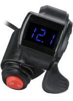
Yeah true, if we had better throttles that were not hall sensor based. Although I’ve found a decent thumb throttle that I use on my stealth bomber clone. It’s still a cheap hall sensor throttle, but I can modulate the throttle with good accuracy, even riding through mud without tire spin. I have found this impossible with trying to use a hall sensor twist throttle because the torque makes me jerk the throttle more. Also with off-road use I tend to unintentionally twist throttle more through bumpy terrain.
But yeah that being said, I’m sure it would be harder to modulate if I went with the 26s option.

I’ll be using the same cheap thumb throttle on the Rmz conversion and keep and extra with me in case the thumb lever snaps off like I’ve done before in the past 😅
Would be nice if they made a metal version of this particular thumb throttle.

This makes me wonder what type of throttle the stark Varg comes with, especially it being at 340 V nominal.
 

Attachments

  • 49F360C7-7E08-4724-A366-1B030EDE859B.jpeg
    49F360C7-7E08-4724-A366-1B030EDE859B.jpeg
    240.2 KB · Views: 3
It doesn't really have to do with the sensor the throttle uses. It has to do with the response of the controller to the throttle, and on most of those, it's not adjustable and is very basic. (It also has to do with the physical design of the throttle's mechanical throw, as there are some with long throws and some with short; it's a fair bet most typical throttles of either sensor type are short throw making).

Most typical (cheap, especially) controllers do speed control, so the throttle directly controls the average voltage to the motor. Current to the motor, or it's torque, is a byproduct of how much voltage you're applying to it, so to get high torque you have to blip the throttle all the way up.

A better controller (FOC controller, for instance) will have the throttle modulate current of the motor directly, so directly controling the torque of the motor, and the response to the throttle is usually very different.

If it is a torque-controlling throttle the controller probably has the ability to select from various throttle curves, or adjust it's response to throttle input, such that the rider has better control in various situations.

As for the pot vs hall throttle types....you can also use cable-operated types of either, which can come in linear or rotary versions, and then use whatever type of hand control that pulls the cable that you want, and even use a pulley between them (along the lines of the Problem Solver, though not that exact one), to alter the amount of sensor movement vs cable pull.


Over in my SB Cruiser thread you can find a post showing how I setup a metal ATV cable-pulling thumb throttle that pulls a cable to a cheap rotary hall throttle body's pulley (COT, cable-operated throttle). I did this because I was royally and completely tired of breaking the tabs off of plastic thumb throttles, but I got much better and smoother operation out of it in the process.

I also use a brake lever to pull a second COT to modulate the variable regen of a Grinfineon controller (via the CA as well, using a relay switched by pulling the ebrake lever to switch which throttle feeds the CA).

Side note probably also relevant here: I need to replace the cable now because I damaged it or hte housing recently while fixing something else, so ti sometimes catches and doesn't fully release the throttle....but because the Cycle Analyst (that processes my PAS and throttle and other sensor inputs to provide a throttle control signal to the 2WD system) has a fully adjustable throttle in and out setup, I just tweaked the in a bit to not respond to the voltage that comes from the COT unit within the range it can get stuck in, preventing any runaway problems until I can fix the cable. ;)
 
Last edited:
Does anyone have recommendation for cell holders for the, Molice 21700 P42A?

I’ve purchased some sell holders from 18650 battery.com but they are too loose. Chatted with their customer service and he says that the smaller version that they sell fit but it’s an extremely tight fit so I’m not so confident in ordering those. I see some people don’t use cell spacers and they just hot glue the battery cells together but it seems like it would be much harder to replace a bad cell if that ever occurs, thoughts?

I don’t have a 3-D printer or access, so I need to purchase premade cell spacers.
 
I’ll be using the same cheap thumb throttle on the Rmz conversion and keep and extra with me in case the thumb lever snaps off like I’ve done before in the past 😅
Would be nice if they made a metal version of this particular thumb throttle.

This makes me wonder what type of throttle the stark Varg comes with, especially it being at 340 V nominal.
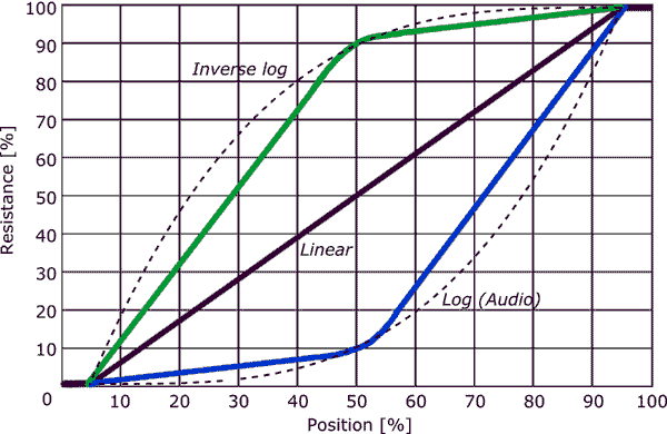
I haven't tried a potentiometer based throttle yet, but was wondering, and maybe someone who uses one knows, if they potentiometer is a simple linear type or if they are nonlinear (log, inverse log). I'd like to see a logarithmic pot throttle to make the lower range output more controllable. I can use my CA to introduce delays or emulate the different throttle control types, etc., but I'd rather have direct control.

potentiometer_taper.png
 
Eastwood, two other options are:
1. RTV. Some even use the electrically insensitive stuff, but others just use generic RTV. Easier to get apart than hot glue and may be more thermally isolating as well.
2. Tape. Some use a two side adhesive tape. Do some digging as I haven't used it but have thought about it. I tend to prefer separates because they introduce more air gap for heat dissipation even thought the battery ends up being fractionally bigger for critical BMS clearance which can be challenging. As you consider the structure of your battery inside the enclosure of course, much of the structural strength of the battery is derived by the nickel strips which act kind of like a trellis or lattice frame for support. So don't need a lot of glue or adhesive strength between cells to keep the cells in place.
So a couple of options...

PS. you can also shim one side or both of the battery diameter with electrical tape to fit inside the holders to act as a shim...but yes, you don't want your cells rattling over bumps and not good for the cells either. A small square of electric tape inside the one end of the holder hole per cell should work.
 
PS. you can also shim one side or both of the battery diameter with electrical tape to fit inside the holders to act as a shim...but yes, you don't want your cells rattling over bumps and not good for the cells either. A small square of electric tape inside the one end of the holder hole per cell should work.
Yes, I’ve been playing with this idea of using electrical tape as a spacer to get the cells to fit more tightly. I’ve purchased just 4 Molicel cells, and have been playing around with what I’ll be able to fit as far as width between the main frame.
Eastwood, two other options are:
1. RTV. Some even use the electrically insensitive stuff, but others just use generic RTV. Easier to get apart than hot glue and may be more thermally isolating as well.

Yeah RTV seems like a good option, but is there any drawbacks to not using cell spacers? I’ve heard random comments, suggesting how dangerous it is to not use cell spacers, but like you mention the actual nickel strips act as a structural support like trellises. If I didn’t use cell spacers, this would definitely give me a smaller battery because of the gap between the cells with using cell spacers. Plus it would give me more room to fit a BMS attached to the battery. The BMS is more than likely will have to be on top of the pack, because I’m already maxed out with widths d depth. There’s hardly any allowance with creating two walls of battery cells stacked beside each other.

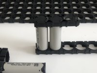
As you can see in the picture below, there’s a huge gap between the cells with using the cell spacers, which takes up a lot of room when you’re talking about 340-ish 21700 cells.

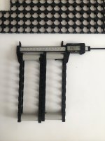
2nd pic will be the width of the pack so I can pull the battery out from the top of the frame. The battery will be longer/taller.
 

Attachments

  • ED11D1F0-D0D4-4AC9-AF04-6EC5FA7BA0CC.jpeg
    ED11D1F0-D0D4-4AC9-AF04-6EC5FA7BA0CC.jpeg
    1.5 MB · Views: 8
  • 37D20053-089B-4C0B-8596-BCC71A3B0263.jpeg
    37D20053-089B-4C0B-8596-BCC71A3B0263.jpeg
    1 MB · Views: 7
Last edited:
I have a 52V Chinese battery right now that will handle 45a where the 21700 cells are glued together and a tight fit in a Reention shark enclosure.
Works fine. Ideally, I think battery cell spacers are the best option for heat dissipation. In your shoes if packaging permits, I would simply use a square of electrical tape in each spacer hole to create a light interference.
Probably be ok either way.
 
Cell spacers to keep the bodies of the cells apart so they can't short across their series connection is a good idea, too, (without them vibration could eventually rub the cells together until they wear thru their shrinkwrap and short the cans together).
Is this the main reason for using cell spacers, so they don’t vibrate together and wear through the shrink wrap and short Circuit?
 
Is this the main reason for using cell spacers, so they don’t vibrate together and wear through the shrink wrap and short Circuit?
Well yes...
For structural rigidity of keeping the cells in place.
For uniform air gap thereby removing any heat conduction potential and allowing thermal convention between cells
And a tertiary method of organization and means of determining if all the cells will fit inside the enclosure. Cut the cell dividers such that they house all the batteries you need to satisfy your series and parallel requirements for voltage and capacity, put a few cells in place on the ends and assemble the battery case and see if they will all fit. Much harder to do in a freer format where you are gluing the batteries together and after you glue them together, they may not fit all in the case and then you have a big mess on your hands disassembling the cells. So it allows a dress rehearsal of what will fit inside your battery case if that makes sense.
 
The spacers do that--spacing the cells apart, but they also hold them at the same distance apart, so they can't flex around and break spotwelds or other interconnects, etc.

I expect that packs built with spacers that actually keep the cells held together / in place make for better pack safety than the old "hot glue and duct tape" packs like the CammyCC pack I did what I could to repair something like a decade ago.

OK gotcha, i’ll stick with using cell spacer 👍
I actually ordered some new spacers earlier that should be a better fit then the ones I got from 18650 battery.com..

But before I even think about ordering 340-ish cells, I need to sort out a spot welder. From reading on here and seeing many YouTube videos it looks like the diy Kweld is the best option. I would much rather buy a premade spot welder, but from the research I’ve been doing it seems like the welds are too weak from the spot welders that are a few hundred dollars. Unless you, or anyone else has suggestions of a spot welder, I could buy that simply plugs into AC power source.

I have about 20 old cells of 18650s that I can practice on before I start actually assembling my pack. Just seems like another headache, that I have to DIY the spot welder, and then figure out a darn power supply 😅. But at the end of the day, I will be building a powerful battery pack, and I don’t want weak spot weld creating more resistance, or the spot welds pulling apart from vibration, etc.
 
340 cells is a monster battery whereby most ebike batteries are about 1/5 th that size. Can you share what config of battery and bike you will be powering with such a large battery? Have you determined a cell brand and model for your build and/or a source?
 
Back
Top