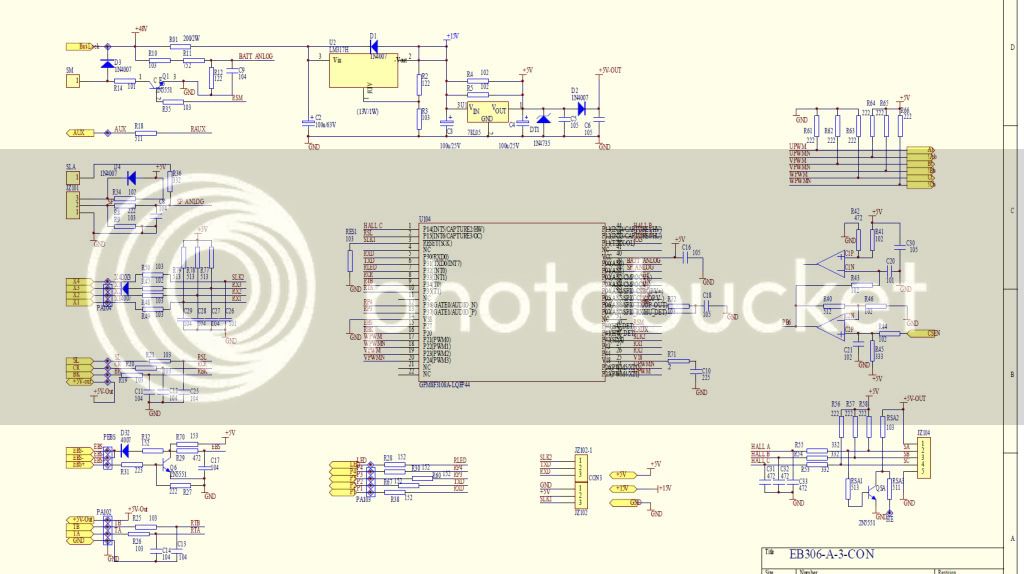
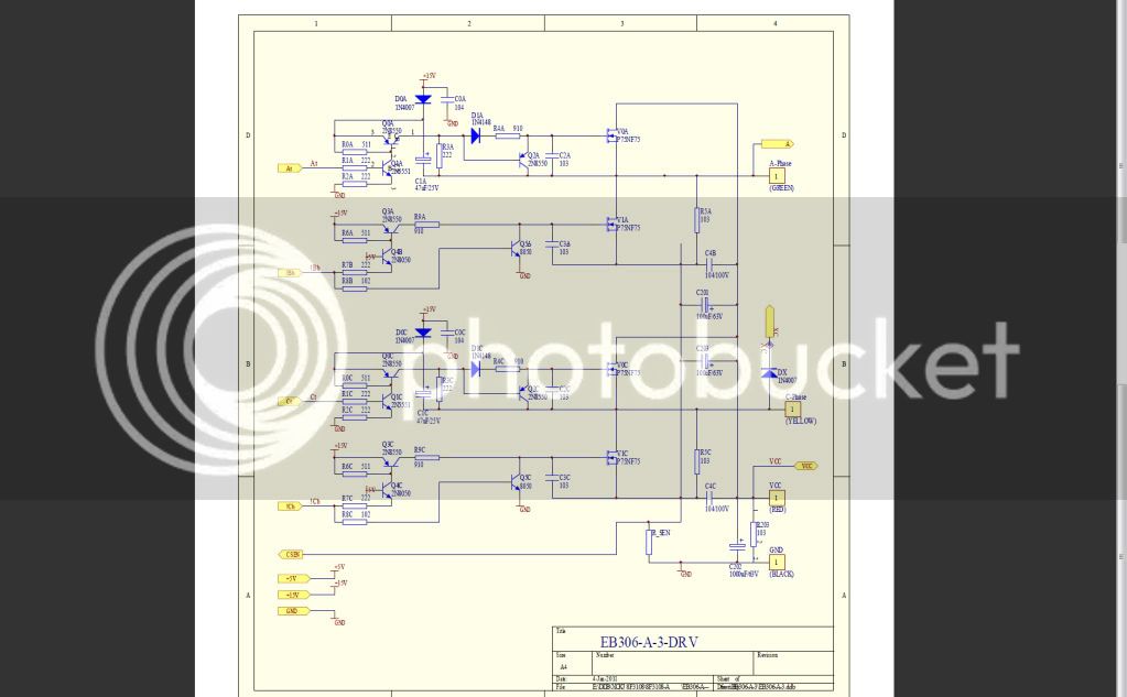
#$%@$#@ <--- (insert favorite swearword here), IT WORKS !!!!

Hi,

How difficult would it be and how beneficial would it be to add the capability of accepting input from sin/cos sensors, in addition to hall sensors? Seems like a good match for this project because the sin/cos sensors work better at low speed:
http://endless-sphere.com/forums/viewtopic.php?f=28&t=34628&p=503866
liveforphysics said:
bigmoose said:
Two nice things about the sin/cos sensor:
  • It get the position sensing element out of the stator heat flux
  • It allows precise timing advance with the right controller just like a timing map in an IC ECM


Yes sir it does. We did it mainly for the heat reason you mentioned, as hall melting failure was our demise at the last race event, as well as a previous race.

The second reason you mentioned wasn't really something we were needing for this application, but WOW! It just make it silky smooth, no more chug-chug-chug at low RPM's as each hall sensor latches and tells the fets to switch the next coil on, it's just silky now, you can make the motor spin so slowly you can barely see it moving at all, and it's just perfectly smooth with no torque ripple noticed at all now. Really feels like electric power should feel at all RPM's rather than little bumps of torque pulses when you're at low speeds.

It's fun having this much torque too, I just nosed the front wheel up to a staircase outside a strip mall, and in a very slow controlled calm way, just torqued up the 10 stairs or so and rode along the sidewalk path at the top. It felt even easier than walking up stairs, though the seat does kinda smash into your ass as the rear tire goes over each step. I don't know that it would have been possible to do it so effortlessly on hall sensors.
 
MitchJi said:
Hi,

How difficult would it be and how beneficial would it be to add the capability of accepting input from sin/cos sensors, in addition to hall sensors? Seems like a good match for this project because the sin/cos sensors work better at low speed:
http://endless-sphere.com/forums/viewtopic.php?f=28&t=34628&p=503866

I don't see any benefit in using sin/cos sensors.

- whatever position sensor system you use, it will always be as accurate as the person whole placed it.
- under load timing will always be wrong as timing depends on many things, only (hall-) sensorless can have perfect timing.
- I make the transition to sensorless around 60 to 120 e-rpm anyway.

And, not unimportant, I already used all the analog inputs (all 9 of 'm) :oops: I'm assuming its an analog-out sensor ?
 
Hi Lebowski,

MitchJi said:
How difficult would it be and how beneficial would it be to add the capability of accepting input from sin/cos sensors, in addition to hall sensors? Seems like a good match for this project because the sin/cos sensors work better at low speed:
http://endless-sphere.com/forums/viewtopic.php?f=28&t=34628&p=503866

Lebowski said:
I don't see any benefit in using sin/cos sensors.
- whatever position sensor system you use, it will always be as accurate as the person whole placed it.
- under load timing will always be wrong as timing depends on many things, only (hall-) sensorless can have perfect timing.
- I make the transition to sensorless around 60 to 120 e-rpm anyway.
I wasn't thinking of better accuracy. I was thinking of better low speed performance:
liveforphysics said:
The second reason you mentioned wasn't really something we were needing for this application, but WOW! It just make it silky smooth, no more chug-chug-chug at low RPM's as each hall sensor latches and tells the fets to switch the next coil on, it's just silky now, you can make the motor spin so slowly you can barely see it moving at all, and it's just perfectly smooth with no torque ripple noticed at all now. Really feels like electric power should feel at all RPM's rather than little bumps of torque pulses when you're at low speeds.
It would be nice to have completely a perfectly smooth motor starting up, when its "spin[ing] so slowly you can barely see it moving at all" all the way up to perfect timing at WOT. I assume when Luke says "WOW!" about low speed performance it must be pretty nice, since its not an issue he is normally concerned with. So it seems like its potentially an excellent combination, great low speed and great high speed performance.

Lebowski said:
And, not unimportant, I already used all the analog inputs (all 9 of 'm) :oops: I'm assuming its an analog-out sensor?
It depends on which one you use. They are available with digital outputs (both of Todd's links have options with digital outputs):
Thud said:
I am pretty certain they grabbed an off the shelf rotary encoder for reading position. a quick google brings up several that could be employed with a little creativity:
http://www.quantumdev.com/products/optical_encoders/sc12.html
http://ab.rockwellautomation.com/Motion-Control/Sine-Cosine-Absolute-Encoder
quantumdev said:
Output Circuits
(A) Sine/Cosine, Index & RS422 UVW (TTL Compatible)
(B) Sine/Cosine, Index & UVW Open Collector
But I suspect I'm overlooking a potential problem, or that it will be more work to implement than its worth because if it was a good idea, and the benefits outweighed the work involved someone else would probably have jumped in to support the idea.

Thanks!
 
I looked at the links of the sensors, the difficulties I see are

- the sensor needs to be matched to the number of poles in the motor. One of them is available in 4,6 or 8 poles, I have
14 poles.
- how would you (mechanically) connect something like that in a hub motor ?
- since I switch to sensorless at a low rpm it would only offer a (questionable) advantage at startup

Maybe an interface for such a sensor would be a good idea when they come standard in the hubmotors 80% of us use but even
then, I feel for high power and difficult motors (any motor) sensorless is the only way...
 
I'm trying to think of any of our high performance industrial BLDC motors that use sensorless (at work). I can't think of any. I think of all the folks who have tried sensorless on ES, and they always seem to have problems. Low RPM, high load, high RPM, high power, coasting, accelerating hard, decelerating quickly, regen, operating in field weakening mode or back EMF greater than supply voltage - they always have regions of difficulty where the sensorless becomes unsynchronized or produces less performance than hall sensors did. So for rock reliable never out of synch operation under the full range of conditions sensorless seems to fail.

On the other hand, we have exactly one example that I'm aware of on ES of sin/cos encoder operation - it is not compatible with a hubmotor (though Amber's wheelchair motor has it and it is sort of a hubmotor?), and as you point out finding an encoder to match the pole count is not always easy, though opticals can be set up for any pole count.

I suppose the Variable Frequency Drives could be said to be "sensorless", and they seem to work fine. I believe they look at current rather than voltage, so perhaps vector control works better than back EMF sensorless. They also model the motor and have the data for inductance and resistance and motor temperature so they can compensate more accurately for dynamics.

So thinking about this I agree with you - sin/cos encoders are probably not worthwhile to worry about at this point - but I also suspect that getting sensorless operation to be perfect seems to be more difficult than expected and I don't think we've seen any controllers yet that have succeeded. I wonder if Justin of ebikes.ca's sensorless operation is without problems... Burtie's timing advance unit seems to have difficulties as well, but he is working through them. Perhaps it only takes a couple of years of tweaking to get it right.

So what do you think - is your sensorless control algorithm having or going to have regions of difficulty?
 
Alan B said:
So thinking about this I agree with you - sin/cos encoders are probably not worthwhile to worry about at this point - but I also suspect that getting sensorless operation to be perfect seems to be more difficult than expected and I don't think we've seen any controllers yet that have succeeded. I wonder if Justin of ebikes.ca's sensorless operation is without problems... Burtie's timing advance unit seems to have difficulties as well, but he is working through them. Perhaps it only takes a couple of years of tweaking to get it right.

So what do you think - is your sensorless control algorithm having or going to have regions of difficulty?

Interesting question :D where would my algorithm have difficulties. I'll keep thinking about this question
but at the moment there's only one significant (though unlikely) one I can think of. There may be trouble with
a high impedance motor (who wants that ?) running at a low speed where it produces very little back-emf

Another thing (also highly unlikely) is that the control loops (who's parameters are accessible and can be set over RS232
by the user, so lots of playing around room) lose it. If you manage to slow down / speed up the motor significantly
in a matter of milliseconds then the loops might lose lock, though... If the phase loop cannot keep up with accelleration
the timing will be off by such an extent that the motor cannot accelerate, an equilibrium will be found I imagine.
 
eb306-a.jpg
 
It took me a while , sorry. iS THIS WHAT YOU WANTED FOR 306 BOARDS ? if you want pdf files , send me your mail adress
Sweet work , keep on man ..
 
Hi,

Lebowski said:
I looked at the links of the sensors, the difficulties I see are...

I feel for high power and difficult motors (any motor) sensorless is the only way...
Just to be clear I suggested the sensors to replace the Halls, not the sensorless.

Alan B said:
So thinking about this I agree with you - sin/cos encoders are probably not worthwhile to worry about at this point - but I also suspect that getting sensorless operation to be perfect seems to be more difficult than expected and I don't think we've seen any controllers yet that have succeeded.

recumpence said:
#1 If you are talking about a sensorless controller, good luck. MANY people have tried and it would be tough to improve on the Castle Creations controllers we are using for sensorless RC stuff. It is not impossible, but would cost a lot to do. Sensored is another thing altogether. :)
For motor control the Castle controllers work very well except for high power/low speed, particularly startup and the resulting amp surges. The reason they are so fragile in general is they are not designed or intended (not heavy duty enought) for ebike use. If Lebowski's unit works comparably well as the Castle for higher speeds, and is used in conjunction with sensors to solve the startup issues and is combined with heavier duty parts to address the Castle's fragility it would be an almost perfect solution.

I say almost because it would clearly be even a little better with sine/cosine sensors instead of halls :wink: :mrgreen:. I'm sorry Lebowski, I couldn't resist.
 
what are the reasons for changing from halled to sensorless once the motor is running?
 
whatever said:
what are the reasons for changing from halled to sensorless once the motor is running?
In this case hall sensors are the worst option for higher rpm. Lebowski is feeding the coils with kind of alternating current (AC) which makes smooth and efficient run and is timed by analog BEMF. Hals (we usually use) are kind of digital switches good for on/off position.
 
whatever said:
what are the reasons for changing from halled to sensorless once the motor is running?

What Parabellum said is part of the answer. It is virtually impossible to place hall sensors in the
correct location and to get the timing spot on. Plus there is much more than just the rotor position
determining the correct timing. You also need to take into account rotor speed, amount of power
being delivered, hell, the only thing timing does not depend on is the position of the sun and the moon :D

Sensorless is the only way to get the timing correct. I treat sensored operation as something you do
to get torque at 0 standstill and at very low rpm to dial in the sensorless control loop, once that's done
sensorless takes over.

Another thing about sensored... My 30F controller real-time outputs all kinds of loop parameters during motor
operation. I was shocked to see how un-even my motor was built, from the data I could exactly see which
magnets and coils were out of position. I expect the same to be true for commercial motors, maybe to
a lesser extent but still.. How are you going to place your hall sensors correctly when the magnets in
the motor are un-evenly spaced ?
 
I think even commercial motors (at least typical ebike motors) have significant position error in the hall sensors. I'm not sure how much this affects efficiency, but it can't be good.

It would be interesting to see how much improvement there is between a typical chinese controller and Lebowski's design under actual operation conditions.

By getting the timing exactly right, there could be a significant reduction in motor heating as it won't be fighting itself so much.
 
When we were talking to motor testing facility in Slovenia the answer was : even a smallest misalignment affects efficiency alot
 
small status update

I've put in dual polinomal throttles. You can use either 1 or 2 analog throttles and have the option to TX the
data from these over CAN to a slave controller, or RX throttle info over CAN and use it. The shape
of the polinomal throttle curves can be independent for master and slave, also the maximum
phase current can be independen (like if you have a 350W Mac in the front and a 500W Mac in
the rear, you can control these from one throttle with independent response curves)

With the polinomal you can construct exponential, linear or square-root type throttle curves.
The last few days I read on the forum about how people set independently the maximum phase
current and the maximum battery current. Since I only deal with phase currents (and max-phase
current) I'm now busy putting in a conversion equation which calculates the battery current
based on phase current and PWM signals. Then I'll be able to put in a battery current limiter,
I'll put a limit for current drawn from the battery (motor use) and a second limit for maximum regen-current.
 
how will the programming of all parameters be handled? will there be a pc configuration application?

it would also be nice to have the feature you posted on the first post here:
http://www.endless-sphere.com/forums/viewtopic.php?f=2&t=31889&hilit=limiter&start=62

I would do it more sneaky... if throttle is in full speed position when powering up the controller -> unrestricted mode, if throttle
is anywhere else -> legal mode. Then you can give the bike to a cop to try and be sure it's in legal mode while it's still
easy and unnoticable when you turn it on for high power mode
 
nieles said:
how will the programming of all parameters be handled? will there be a pc configuration application?

Programming of all parameters goes over RS232 (or in my case with my laptop, over a USB<->RS232 cable) and a simple
terminal program. This is a 'session' which I saved, it shows what it looked like about a month ago (much more parameters now):

Code:
#######################################

 (c)opyright 2011, xzt06sd@hotmail.com 

#######################################


1) calibrate hall sensors
2) determine coil positions
3) change PWM parameters
9) store parameters in EEPROM for motor use

------> 1 

1) calibrate hall positions
2) change # of e-cycles
8) table out hall signals
9) return to main menu

# of e-cycles to be used:65535

------> 2 

new value -> 14 

1) calibrate hall positions
2) change # of e-cycles
8) table out hall signals
9) return to main menu

# of e-cycles to be used:14

------> 1 

Spin the motor then press any key to start measurement
1
2
3
4
5
6
7
8
9
10
11
12
13
14

1) calibrate hall positions
2) change # of e-cycles
8) table out hall signals
9) return to main menu

# of e-cycles to be used:14

------> 8 

hall 1, hall 2, hall 3
.500	.520	.540
.500	.520	.540
.500	.520	.540
.500	.520	.540
.500	.520	.540
.500	.520	.540
.500	.520	.540
.500	.520	.540
.500	.520	.540
.500	.520	.540
.500	.520	.540
.500	.520	.540
.500	.520	.540
.500	.520	.540
.500	.520	.540
.500	.520	.540
.500	.520	.540
.500	.520	.540
.500	.520	.540
.500	.520	.540
.500	-.520	.540
.500	-.520	.540
.500	-.520	.540
.500	-.520	.540
.500	-.520	.540
.500	-.520	.540
.500	-.520	.540
.500	-.520	.540
.500	-.520	.540
.500	-.520	.540
.500	-.520	.540
.500	-.520	.540
.500	-.520	.540
.500	-.520	.540
.500	-.520	.540
.500	-.520	.540
.500	-.520	-.540
.500	-.520	-.540
.500	-.520	-.540
.500	-.520	-.540
.500	-.520	-.540
.500	-.520	-.540
.500	-.520	-.540
.500	-.520	-.540
.500	-.520	-.540
.500	-.520	-.540
.500	-.520	-.540
.500	-.520	-.540
.500	-.520	-.540
.500	-.520	-.540
.500	-.520	-.540
.500	-.520	-.540
.500	-.520	-.540
.500	-.520	-.540
.500	-.520	-.540
.500	-.520	-.540
.500	-.520	-.540
.500	-.520	-.540
.500	-.520	-.540
.500	-.520	-.540
.500	-.520	-.540
.500	-.520	-.540
-.500	-.520	-.540
-.500	-.520	-.540
-.500	-.520	-.540
-.500	-.520	-.540
-.500	-.520	-.540
-.500	-.520	-.540
-.500	-.520	-.540
-.500	-.520	-.540
-.500	-.520	-.540
-.500	-.520	-.540
-.500	-.520	-.540
-.500	-.520	-.540
-.500	-.520	-.540
-.500	-.520	-.540
-.500	-.520	-.540
-.500	-.520	-.540
-.500	-.520	-.540
-.500	-.520	-.540
-.500	-.520	-.540
-.500	-.520	-.540
-.500	-.520	-.540
-.500	-.520	-.540
-.500	-.520	-.540
-.500	-.520	-.540
-.500	.520	-.540
-.500	.520	-.540
-.500	.520	-.540
-.500	.520	-.540
-.500	.520	-.540
-.500	.520	-.540
-.500	.520	-.540
-.500	.520	-.540
-.500	.520	-.540
-.500	.520	-.540
-.500	.520	-.540
-.500	.520	-.540
-.500	.520	-.540
-.500	.520	-.540
-.500	.520	-.540
-.500	.520	-.540
-.500	.520	-.540
-.500	.520	-.540
-.500	.520	.540
-.500	.520	.540
-.500	.520	.540
-.500	.520	.540
-.500	.520	.540
-.500	.520	.540
-.500	.520	.540
-.500	.520	.540
-.500	.520	.540
-.500	.520	.540
-.500	.520	.540
-.500	.520	.540
-.500	.520	.540
-.500	.520	.540
-.500	.520	.540
-.500	.520	.540
-.500	.520	.540
-.500	.520	.540
-.500	.520	.540
-.500	.520	.540
-.500	.520	.540
-.500	.520	.540
-.500	.520	.540
-.500	.520	.540


1) calibrate hall positions
2) change # of e-cycles
8) table out hall signals
9) return to main menu

# of e-cycles to be used:14

------> 9 


1) calibrate hall sensors
2) determine coil positions
3) change PWM parameters
9) store parameters in EEPROM for motor use

------> 2 

1) calibrate coil positions
2) change # of back-emf samples
3) reconstruct waveforms based on extracted parameters
8) table out data arrays
9) return to main menu

# of back-emf samples to be used for coil calibration:65535

------> 2 

new value -> 850 

1) calibrate coil positions
2) change # of back-emf samples
3) reconstruct waveforms based on extracted parameters
8) table out data arrays
9) return to main menu

# of back-emf samples to be used for coil calibration:850

------> 1 

Spin the motor then press any key to start measurement

 coil position capture successfull
 data arrays now contain sampled back-emf waveforms

1) calibrate coil positions
2) change # of back-emf samples
3) reconstruct waveforms based on extracted parameters
8) table out data arrays
9) return to main menu

# of back-emf samples to be used for coil calibration:850

------> 8 

data A, data B, data C
.759	.134	-.891
.728	.189	-.909
.699	.236	-.920
.669	.283	-.927
.636	.325	-.933
.601	.366	-.939
.567	.408	-.941
.530	.447	-.941
.491	.488	-.937
.451	.524	-.933
.409	.559	-.928
.364	.593	-.921
.320	.625	-.911
.274	.658	-.898
.226	.686	-.883
.175	.715	-.869
.126	.741	-.849
.073	.765	-.831
.023	.787	-.810
-.028	.810	-.787
-.078	.829	-.760
-.125	.846	-.738
-.187	.864	-.703
-.261	.886	-.655
-.310	.896	-.624
-.356	.906	-.588
-.401	.914	-.552
-.444	.919	-.514
-.485	.922	-.476
-.526	.922	-.436
-.563	.922	-.394
-.600	.918	-.351
-.635	.913	-.308
-.666	.906	-.261
-.699	.894	-.218
-.726	.883	-.170
-.755	.869	-.125
-.776	.856	-.082
-.815	.829	-.0010
-.838	.810	.038
-.858	.788	.088
-.877	.766	.136
-.895	.741	.182
-.911	.715	.230
-.924	.687	.277
-.935	.658	.322
-.947	.625	.365
-.954	.593	.409
-.959	.559	.449
-.962	.524	.490
-.961	.488	.529
-.962	.447	.564
-.959	.407	.599
-.952	.367	.633
-.944	.327	.666
-.933	.283	.693
-.920	.239	.724
-.906	.194	.751
-.891	.145	.774
-.871	.099	.799
-.853	.051	.819
-.831	.001	.839
-.808	-.047	.858
-.778	-.107	.878
-.743	-.167	.895
-.714	-.212	.908
-.685	-.259	.917
-.654	-.305	.925
-.621	-.343	.932
-.587	-.387	.934
-.552	-.428	.935
-.514	-.468	.933
-.474	-.505	.931
-.432	-.540	.927
-.389	-.576	.920
-.346	-.610	.909
-.299	-.641	.899
-.253	-.673	.885
-.204	-.702	.870
-.155	-.729	.854
-.103	-.753	.835
-.052	-.777	.813
-.002	-.799	.792
.049	-.819	.766
.099	-.837	.741
.151	-.854	.715
.196	-.869	.684
.240	-.881	.660
.316	-.897	.608
.361	-.908	.573
.406	-.914	.537
.448	-.918	.499
.489	-.922	.460
.528	-.922	.421
.564	-.921	.378
.601	-.915	.338
.636	-.910	.295
.668	-.902	.249
.699	-.891	.204
.727	-.880	.156
.752	-.866	.108
.780	-.849	.063
.803	-.832	.013
.825	-.813	-.035
.848	-.791	-.080
.864	-.772	-.122
.887	-.740	-.186
.903	-.715	-.232
.916	-.688	-.278
.930	-.657	-.323
.940	-.626	-.367
.946	-.593	-.409
.951	-.560	-.449
.954	-.524	-.489
.954	-.486	-.528
.953	-.451	-.564
.950	-.410	-.599
.943	-.370	-.633
.934	-.328	-.665
.924	-.286	-.693
.910	-.242	-.721
.897	-.196	-.748
.882	-.149	-.772
.864	-.102	-.795
.843	-.056	-.817
.821	-.008	-.836
.799	.041	-.854
.773	.088	-.870

1) calibrate coil positions
2) change # of back-emf samples
3) reconstruct waveforms based on extracted parameters
8) table out data arrays
9) return to main menu

# of back-emf samples to be used for coil calibration:850

------> 3 

 data arrays now contain reconstructed back-emf waveforms

1) calibrate coil positions
2) change # of back-emf samples
3) reconstruct waveforms based on extracted parameters
8) table out data arrays
9) return to main menu

# of back-emf samples to be used for coil calibration:850

------> 8 

data A, data B, data C
.743	.154	-.923
.715	.205	-.937
.686	.255	-.948
.656	.303	-.958
.623	.349	-.964
.589	.394	-.968
.554	.437	-.969
.516	.478	-.968
.477	.518	-.964
.436	.556	-.958
.393	.592	-.949
.350	.627	-.939
.305	.661	-.928
.259	.693	-.914
.211	.724	-.899
.163	.753	-.883
.114	.781	-.864
.063	.806	-.843
.012	.831	-.820
-.040	.853	-.794
-.093	.874	-.765
-.146	.893	-.734
-.199	.910	-.701
-.251	.925	-.666
-.302	.938	-.628
-.352	.949	-.590
-.399	.958	-.550
-.444	.964	-.509
-.486	.968	-.468
-.526	.969	-.426
-.563	.968	-.383
-.598	.964	-.340
-.631	.957	-.295
-.663	.948	-.249
-.692	.937	-.202
-.721	.924	-.153
-.749	.909	-.103
-.775	.892	-.052
-.800	.874	-.000
-.824	.854	.051
-.846	.831	.102
-.866	.807	.154
-.885	.782	.204
-.901	.754	.253
-.915	.724	.301
-.926	.693	.347
-.935	.660	.392
-.942	.625	.436
-.947	.589	.477
-.950	.552	.518
-.950	.513	.556
-.949	.474	.594
-.945	.433	.629
-.940	.390	.663
-.932	.347	.695
-.921	.302	.725
-.909	.255	.754
-.894	.207	.780
-.878	.158	.805
-.859	.107	.829
-.839	.055	.851
-.817	.003	.871
-.794	-.049	.890
-.769	-.102	.907
-.743	-.154	.923
-.715	-.205	.937
-.686	-.255	.948
-.656	-.303	.957
-.624	-.349	.964
-.589	-.394	.968
-.554	-.437	.969
-.516	-.478	.968
-.477	-.518	.964
-.436	-.556	.958
-.394	-.593	.949
-.350	-.628	.939
-.305	-.661	.927
-.259	-.693	.914
-.212	-.724	.899
-.163	-.753	.882
-.114	-.781	.864
-.063	-.806	.843
-.012	-.831	.820
.040	-.853	.794
.093	-.874	.765
.146	-.893	.734
.199	-.910	.701
.251	-.925	.665
.302	-.938	.628
.352	-.949	.590
.399	-.958	.550
.444	-.964	.509
.486	-.968	.468
.526	-.969	.426
.563	-.968	.383
.598	-.964	.340
.631	-.957	.295
.662	-.948	.249
.692	-.937	.201
.721	-.924	.153
.748	-.909	.103
.775	-.893	.052
.800	-.874	.000
.824	-.854	-.051
.846	-.832	-.103
.866	-.808	-.154
.885	-.782	-.204
.901	-.754	-.253
.915	-.725	-.301
.926	-.693	-.348
.935	-.660	-.392
.942	-.626	-.436
.947	-.590	-.478
.950	-.552	-.518
.950	-.514	-.557
.949	-.474	-.594
.945	-.433	-.629
.939	-.391	-.663
.931	-.347	-.695
.921	-.302	-.725
.909	-.256	-.754
.894	-.208	-.780
.878	-.158	-.805
.859	-.107	-.829
.839	-.055	-.851
.817	-.003	-.871
.794	.049	-.890
.769	.101	-.907

1) calibrate coil positions
2) change # of back-emf samples
3) reconstruct waveforms based on extracted parameters
8) table out data arrays
9) return to main menu

# of back-emf samples to be used for coil calibration:850

------> 9 


1) calibrate hall sensors
2) determine coil positions
3) change PWM parameters
9) store parameters in EEPROM for motor use

------> 3 

1) change PWM frequency
2) change PWM deadtime
3) change dutycycle PWM test signal
8) test PWM signals
9) return to main menu

PWM frequency: 0kHz
deadtime: 8499ns
dutycycle testsignal: 50%

------> 1 

new value -> 50 

1) change PWM frequency
2) change PWM deadtime
3) change dutycycle PWM test signal
8) test PWM signals
9) return to main menu

PWM frequency: 50kHz
deadtime: 8499ns
dutycycle testsignal: 10922%

------> 2 

new value -> 300 

1) change PWM frequency
2) change PWM deadtime
3) change dutycycle PWM test signal
8) test PWM signals
9) return to main menu

PWM frequency: 50kHz
deadtime: 299ns
dutycycle testsignal: 10922%

------> 9 


1) calibrate hall sensors
2) determine coil positions
3) change PWM parameters
9) store parameters in EEPROM for motor use

------> 9 

 Data stored in EEPROM for motor use


1) calibrate hall sensors
2) determine coil positions
3) change PWM parameters
9) store parameters in EEPROM for motor use

------>

All this text was generated by the 30F, the PC is only send the typed characters over RS232 to the 30F and display what it receives from the 30F.
The tables can be cpoy/pasted into a spreadsheet program to yield graphs.

I don't want to waste my time writing a fance windows GUI interface, plus I like the 80-ies BBS feel of it :mrgreen:
 
fechter said:
I agree. Once you get it dialed in, there should not be much need for tweaking. As long as you can figure out how to enter the parameters properly I don't see a lot of value in a fancy GUI.

Are you planning to have any kind of display?

At the moment there's no setup for a display. There's no reason it shouldn't be possible in a next version though,
there's CAN bus communication so a second controller could ask the motor controller al kinds of questions. First
I'm concentrating on making my bike go :D

What it does have at the moment is RS232 out during motor use. There is 10 to 20 parameters inside the controller
which can be outputted over RS232 at a rate of around 4 kHz. Dependent on which parameter you want to view you
send a letter to the controller. This then starts sending back the 16 bit variable over RS232 to the PC where you can
real-time plot it in a graph (see also the 2nd video of the RC motor, on the laptop screen). It can transmit variables
like e-phase, motor current, control loop variables, effective throttle input, effective PWM amplitude etc etc. Send
another letter and it will output another variable, a letter out-of-range will shut down the RS232. Nifty, eh ?
 
Great work Lebowski! I can't believe the redneck in your avatar is the same guy who built this controller, this has got to be the most advanced piece of redneck engineering yet! :lol:

Redneck= good ol country boys, like the one in Lebowski's avatar.
 
With RS232 output it wouldn't be too hard to make something that works on a Palm Pilot or similar to display useful parameters like current.
 
fechter said:
With RS232 output it wouldn't be too hard to make something that works on a Palm Pilot or similar to display useful parameters like current.
I have a couple rs232 db9 bluetooth adapters you can stream a wireless serial link to a bluetooth device and do what you need.
I set it all up a couple years ago for my roadrunner I can start it outside and sit on the couch and play with the tuning. I was looking at trying to make it work at the track so I can watch the cars I tune from the pits but bluetooth is not great for that.
 
Back
Top