#$%@$#@ <--- (insert favorite swearword here), IT WORKS !!!!

etard said:
Great work Lebowski! I can't believe the redneck in your avatar is the same guy who built this controller, this has got to be the most advanced piece of redneck engineering yet! :lol:

Redneck= good ol country boys, like the one in Lebowski's avatar.

Actually there are 2 persons on the avatar picture, Lebowski could also be the woman :shock:
 
Hugues said:
etard said:
Great work Lebowski! I can't believe the redneck in your avatar is the same guy who built this controller, this has got to be the most advanced piece of redneck engineering yet! :lol:

Redneck= good ol country boys, like the one in Lebowski's avatar.

Actually there are 2 persons on the avatar picture, Lebowski could also be the woman :shock:
There is video on page 5 where you can see Lebowkis reflection in the screen, definitely not the guy on the avatar! :D Thanks God!
 
ctirad said:
Do you plan to make it comercially available some day?

That would be nice :D I don't know about selling complete controllers though it is an attractive
possiblity... At the moment I'm still finishing up the program, after that I'll send chips to people
that want to do beta testing :)

Because I'm also working on this for my own personal bike I'll make a sort of 'reference' design,
I'll post a schematic for how to build a controller with the 30F. This can be used to see how the
30F should be connected (if you want to plug it into an existing XieChang controller) or can be
used to build a controller from scratch. Just ordered $150 worth of 30F's, 4115's, NCP5181's,
20A versions of the ACP714's etc etc on digikey :D

Because of all the configurable variables and options in the controller I'll also write a sort of
manual explaining all the parameters, suggesting values and equations for calculating them.
The suggested equations for the parameters are basic (so if you just want to ride you'll have
no problem setting it up correctly) but allow room for your own experimentations as well.

Just a tip, I went to the town recycling centre last week to get rid of some paper and cardboard. I had
a dig through the electronics bin and found a 100-240V to 16.6 V / 2 Amps laptop charger. I tried
it on 65 V DC and it worked fine. I'll use this on my bike to go from 96V (ping) down to 16.6V
to power the PIC (via 1 Amp version of 7805) and FET drivers.
 
so running sensorless after startup would mean the timing adjustment tool on another thread would not be required, you would be running at ideal timing
no matter the rpm?
 
At 6.000rpm you have 100 revs per second or 10ms per rev.

If the controller needs 100us (how much is this in reality?) for input, processing and output you have an angle failure of 3,6° with a 30P rotor (one pole each 12°) the failure is... ?
 
c_a said:
At 6.000rpm you have 100 revs per second or 10ms per rev.

If the controller needs 100us (how much is this in reality?) for input, processing and output you have an angle failure of 3,6° with a 30P rotor (one pole each 12°) the failure is... ?

10msec per (mechanical) m-rev, 30P -> 10msec/15 = 666 :twisted: usec per e-rev.
input, processing, output takes around 10 to 12 usec -> once every 6.5 degrees of an e-rev....
Your output stage though needs to be able to handle at least 40 to 50 kHz PWM (the 30F
can update it's dutycycle 2 times per PWM period, dutycycle is allowed to change
between rising and falling edge)

With my background and work experience, I could do an FPGA version to go much, much faster :mrgreen:
 
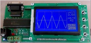
came across this site
http://urun.gittigidiyor.com/elektronik/grafik-lcdli-dspic30f4011-tabanli-osiloskop-39337642
lcd.jpg

seems an lcd screen setup to go with 30f chip ( no idea what language or country its in)
excuse my lack of knowledge on this, but would it be possible to reprogram an xie-cheng chip to do the same as you are doing? is enough known on the xie-cheng chip
another link here referring to lcd with 30f ( i'll delete if not relevant)
http://320volt.com/dspic30f4011-ile-glcd-skop-ve-spectrum-analizor/
 
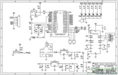
not sure if these diagrams are useful, but seems to be a 30f chip,
from this site
http://www.go-gddq.com/html/PICDanPianJi/2011-02/551855.htm
( i'll delete this post if not relevant: let me know)
2.jpg

 
Yes, the new xie chang boards use new chip. Old boards older chip. We for example have those boards with bigger chip and thats their new standard
 
markobetti said:
Yes, the new xie chang boards use new chip. Old boards older chip. We for example have those boards with bigger chip and thats their new standard
there's a lot of 8's in the name of the chip, is it an 8 bit ? I can't find any datasheet for it.
 
theres a paper
Design and control of a multilevel inverter for electric vehicles
Arthur W. Matteson, Michigan State University
uses the 30f might be worth a read if anyone can find a copy on the net
 
whatever said:
theres a paper
Design and control of a multilevel inverter for electric vehicles
Arthur W. Matteson, Michigan State University
uses the 30f might be worth a read if anyone can find a copy on the net
We already have this going on my thread. See not simple BLDC controller.
I just switched from a dspic30f3010 to a dspic30f4011 mostly for the extra pins for more fetures but also because its more powerfull.
The reason I made it "multylevel" is because I want to be able to swap fets and not have to worry about a fet blowing and making a mess out ot the Brain stage.
I also figure this was I can build a little 6 fet for a bicycle or a multi fet monster for a motorcycle or can and use the same brain design, or even the same brain with a quick reflash!!
 
busy adding the menu's for all the variables.

this is for PWM :
Code:
1) PWM frequency: 21kHz
2) deadtime: 499ns
3) dutycycle testsignal: 50%
4) toggle high side polarity, now active HIGH
5) toggle low side polarity, now active HIGH
8) test PWM signals
9) return to main menu
options 4 and 5 are to adjust whether the controller gives out a logic 1 or 0 to turn
the output stage FETs on. A XieChang has active LOW for the high side FET and
active HIGH for the low side FET. Someone (like me) using NCP5181 drivers
needs both active HIGH.

Code:
1) current sensor transimpedance: 3.32 milli-Ohm
2) maximum motor phase current: 600.0 A
3) maximum battery current, motor use: 350.0 A
4) maximum battery current, regen: 50.0 A
5) maximum shutdown error current, fixed: 10.0 A
6) maximum shutdown error current, proportional: 5.0 A
7) error current filter coefficient: 5
9) return to main menu
Above is the currents setup menu for a high power setup (600 amp sensors as C_A wants
to use), for my testing I use something much more moderate

Code:
1) current sensor transimpedance: 100.00 milli-Ohm
2) maximum motor phase current: 4.0 A
3) maximum battery current, motor use: 1.5 A
4) maximum battery current, regen: 0.0 A
5) maximum shutdown error current, fixed: 0.1 A
6) maximum shutdown error current, proportional: 0.0 A
7) error current filter coefficient: 5
9) return to main menu
The resolution of the currents is 1/32 of an Amp and can go up to 2047 Amps.
Should be enough I think :D
 
Lebowski said:
...Hmmm, that would be something, to turn my algorithm into a custom IC....
This is actually my profession :mrgreen:

I sensed "you knew what you were doing!" Are you an FPGA guy or an ASIC designer?
 
bigmoose said:
Lebowski said:
...Hmmm, that would be something, to turn my algorithm into a custom IC....
This is actually my profession :mrgreen:

I sensed "you knew what you were doing!" Are you an FPGA guy or an ASIC designer?

I'm a principal analog / mixed signal IC design engineer,
If you have a Samsung phone there's a good chance the
Sigma Delta ADC's in it are mine :D I used to be a
research scientist before that at the european equivalent
of Bell Labs (my old lab is most known for inventing the CD)
 
another good article
http://www.eefocus.com/%E8%AE%BE%E8%AE%A1%E6%88%91%E6%9C%80%E8%B5%9E/blog/08-09/155607_39e2c.html
( those % things were chinese characters) goes into some detail on a controller build
 
Back
Top