You are using an out of date browser. It may not display this or other websites correctly.
You should upgrade or use an alternative browser.
You should upgrade or use an alternative browser.
#$%@$#@ <--- (insert favorite swearword here), IT WORKS !!!!
- Thread starter Lebowski
- Start date
Lebowski
10 MW
basically I got the same functionality just not the fancy interface 
Plus a different (better in my opinion) algorithm running the motor
just measured, it takes 9.7 usec to do ADC measurements, compute everything and output the new PWM settings.
Improvement on this number is possible so it will be possible to run at over 100 kHz loop frequency !
Pity processing the analog throttles takes 6 usec, but that's only done 100 times a sec.
liveforphysics
100 TW
Lebowski said:basically I got the same functionality just not the fancy interface
Plus a different (better in my opinion) algorithm running the motor
just measured, it takes 9.7 usec to do ADC measurements, compute everything and output the new PWM settings.
Improvement on this number is possible so it will be possible to run at over 100 kHz loop frequency !
Pity processing the analog throttles takes 6 usec, but that's only done 100 times a sec.
That is really fast Lebowski. Seems like you should be able to control some very sharp rise dI/dT motors with that speed. And run them up to very high RPM. This is exciting stuff.
You can actualy switch between the internal oscilator and an external crystal on the fly, SO I was thinking about running a faster PWM frequency for the startup then at X rpm have it drop down to a lower PWM frequency to help reduce switching losses.liveforphysics said:Lebowski said:basically I got the same functionality just not the fancy interface
Plus a different (better in my opinion) algorithm running the motor
just measured, it takes 9.7 usec to do ADC measurements, compute everything and output the new PWM settings.
Improvement on this number is possible so it will be possible to run at over 100 kHz loop frequency !
Pity processing the analog throttles takes 6 usec, but that's only done 100 times a sec.
That is really fast Lebowski. Seems like you should be able to control some very sharp rise dI/dT motors with that speed. And run them up to very high RPM. This is exciting stuff.
if you change the mpu clock you will change much more than just pwm freq and it may not behave as you expect; i'd recommend changing just the pwm in s/w.
Lebowski
10 MW
passed the 16 Kb of assembly code today 
added the loop coefficients setup menu
busy with the throttle menu
Scroll down in this last one to see the response to menu item '1'.
The coefficients under '3' give a linear response (negative for regen), the ones under '4' model a
exponentional curve with a gentle slope at low throttle and rises sharply for high throttle. But both
can be edited of course.
I still have to put in point '8', am thinking about making it look like an ZX-81 racing game
added the loop coefficients setup menu
Code:
1) loop sample frequency: 40.00 kHz
2) 1st order phase loop integrator coefficient: 0.0709
3) 2nd order phase loop integrator coefficient: 12.7999
4) amplitude loop integrator coefficient: 3.0899
5) maximum amplitude: 120 %
9) return to main menu
busy with the throttle menu
Code:
1) calibrate throttle 1
2) calibrate throttle 2
3) polynomal coefficients throttle 1 (x, x^2, x^3): -1.0000, 0.0000, 0.0000
4) polynomal coefficients throttle 2 (x, x^2, x^3): 0.1022, 0.3842, 0.4982
5) use analog throttle 1: YES
6) use analog throttle 2: NO
   receive throttle over CAN: NO
7) TX throttle over CAN: NO
8) test throttle
9) return to main menu

------> 1

 close or hold slight open throttle 1 for offset measurement
 press any key to begin measurement
 measured voltage: 1174 mV

 fully open throttle 1
 press any key to begin measurement
 measured voltage: 3960 mV
Scroll down in this last one to see the response to menu item '1'.
The coefficients under '3' give a linear response (negative for regen), the ones under '4' model a
exponentional curve with a gentle slope at low throttle and rises sharply for high throttle. But both
can be edited of course.
I still have to put in point '8', am thinking about making it look like an ZX-81 racing game
Just got an email from TI touting their InstaSPIN BLCD solution. Looks like it might be related to the work you are doing as it seems to 'learn' motor parameters. I'm not sure if it's suited for EV drive motors with their varied loading. It may just work well with fans and such. I don't know enough about motor control (yet) to decipher their claims. Anyway, I thought it might be of interest. Here is a link with gobs of information...
http://www.ti.com/ww/en/motor_drive_and_control_solutions/motor_control_instaspin_inside_bldc.htm?DCMP=drv8312&HQS=drv8312-em-lp&sp_rid_pod4=OTA3Njc3NDgzOAS2&sp_mid_pod4=38716875
http://www.ti.com/ww/en/motor_drive_and_control_solutions/motor_control_instaspin_inside_bldc.htm?DCMP=drv8312&HQS=drv8312-em-lp&sp_rid_pod4=OTA3Njc3NDgzOAS2&sp_mid_pod4=38716875
InstaSPIN™-BLDC Solution
In keeping with TI’s philosophy of making motor control more accessible and easier to use by design engineers, TI is proud to announce the release of its newest motor control technology, InstaSPIN-BLDC. Targeted at low cost BLDC applications, InstaSPIN-BLDC is a sensorless control technique based on the premise that “simple is better”. In field tests with over 50 different motor types, InstaSPIN-BLDC was able to get each motor up and running in less than 20 seconds! The reason for this incredible robustness is because InstaSPIN-BLDC doesn’t require any knowledge about motor parameters to work, and you only need to adjust a single tuning value.
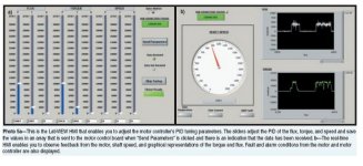
Unlike other sensorless BLDC control techniques based on back-EMF zero-cross timing, InstaSPIN-BLDC monitors the motor’s flux to determine when to commutate the motor. With the help of a free GUI (see figure), the user can watch the flux signal in a plot window, and set the “Flux Threshold” slider to specify at what flux level the motor should be commutated. Optimal commutation can be verified by observing the phase voltage and current waveforms, which are also displayed.
In addition to its ability to work with just about ANY BLDC motor, InstaSPIN-BLDC has demonstrated incredible resilience to speed transient perturbations. With zero-cross timing, you are always using PAST information to predict FUTURE commutation events. But InstaSPIN-BLDC monitors a real-time flux waveform to determine the appropriate time to commutate. Abrupt speed changes will be reflected in the flux waveform in real time, so that it will still cross the specified threshold value at exactly the right time to commutate.
Using flux for commutation vs. back-EMF zero-cross timing also enables more stable operation at lower speeds. Unlike the flux signal, the back-EMF signal amplitude diminishes at lower speeds, resulting in poor signal-to-noise performance. InstaSPIN-BLDC enables smoother operation at low speeds, and provides more reliable motor starting, even under heavy loads.
That Insta-Spin thing sounds very interesting. Thanks for posting the link.
Lebowski
10 MW
why the 20 seconds, why so long ? 
I you look at their document (I only looked at the pictures) (http://www.ti.com/lit/an/sprabn7/sprabn7.pdf)
figure 12 and 14 kind of show it's not a sinewave out typ of solution but it switches like a XieChang does (2 out
of 3 motor wires connected to the battery, 3rd one is floating), the green trace in their plots is a dead give away.
I didn't find any automatic timing advance.
pictures 15/17 showing Ki and Kp, those are what I called 'first / second order integrator coefficient' in the
menu's I posted yesterday
I'm still trying to see how their 'flux measurment' works, as this seems to be a way to get good low speed behavior.
Lebowski
10 MW
I'm impressed by your work Lebowski, and looking forward to follow your progress.
One thing is bugging me, though. You say the motor is driven with true three-phase sinusoidal currents. I like that. But I don't understand how it can be sensorless at the same time. If all phases are continuously driven, then there is never an undriven phase to measure the back-EMF on. Would you like to explain how this works? (or is it part of the secret sauce that you don't want to give away for free?)
One thing is bugging me, though. You say the motor is driven with true three-phase sinusoidal currents. I like that. But I don't understand how it can be sensorless at the same time. If all phases are continuously driven, then there is never an undriven phase to measure the back-EMF on. Would you like to explain how this works? (or is it part of the secret sauce that you don't want to give away for free?)
I don't think its possible to have all three driven all the time... I am pretty sure its just one phase actualy energised at a time. If you try to fire a second or third phase while the first one is still energized it will likely need one of the fets from the oposite side of one of the 2 H bridges besing used in the first phase so it will just creat a pass though event ( you will be turning on a positive fet and a negative fet on the same bridge at the same time and just shorting them out)bearing said:I'm impressed by your work Lebowski, and looking forward to follow your progress.
One thing is bugging me, though. You say the motor is driven with true three-phase sinusoidal currents. I like that. But I don't understand how it can be sensorless at the same time. If all phases are continuously driven, then there is never an undriven phase to measure the back-EMF on. Would you like to explain how this works? (or is it part of the secret sauce that you don't want to give away for free?)
Gordo
100 kW
bearing said:I'm impressed by your work Lebowski, and looking forward to follow your progress.
One thing is bugging me, though. You say the motor is driven with true three-phase sinusoidal currents. I like that. But I don't understand how it can be sensorless at the same time. If all phases are continuously driven, then there is never an undriven phase to measure the back-EMF on. Would you like to explain how this works? (or is it part of the secret sauce that you don't want to give away for free?)
The question does not make sense to me. The current and voltage are switched, (AC) going from zero to maximum and back to zero. Therefore there is back-EMF to measure. Where does the conclusion that true three-phase current is a DC state come from? The phases are driven one at a time, the same as with all BLDC motors. The motor/controller waveform is identical to a sensored setup. The difference is that Lebo does it with an algorithym which takes over at a very low rpm.
c_a
100 W
three phase sinus:
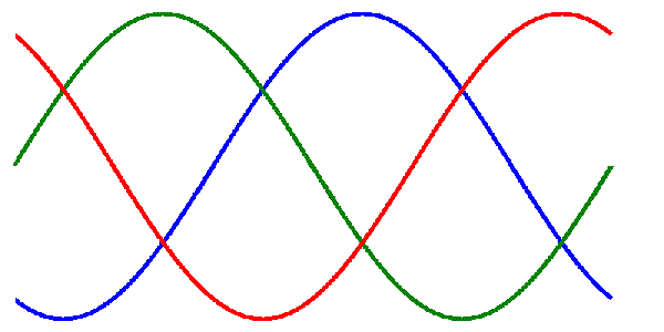
It is impossible to replicate that with 3 H bridges. You only actualy get one peak at a time. Other wise you would get a blown H bridgec_a said:three phase sinus:

Alan B
100 GW
My present understanding:
Sensorless BLDC motor control is generally done with current driven in one motor connection, out another and the third floating connection is used to measure back EMF and determine the commutation point. The drive current could be DC or sinusoidal. It is most efficient if the drive waveform matches the motor waveform which for BLDC is generally DC. A permanent magnet brushless motor that has sinusoidal back EMF is generally not called a BLDC motor but is instead called a PMSM (permanent magnet synchronous motor).
In three phase sensorless drive the phase current/voltage relationships are used to determine the rotor position since all three phases have driven current and back EMF is obscured by the drive voltages.
Gordo
100 kW
Alan B said:My present understanding:
In three phase sensorless drive the phase current/voltage relationships are used to determine the rotor position since all three phases have driven current and back EMF is obscured by the drive voltages.
Are the SOIC ACS714-20 current sensors used because the back EMF can't be seen?
Here is one way to do it (sensored). (With three half bridges.)Arlo1 said:It is impossible to replicate that with 3 H bridges. You only actualy get one peak at a time. Other wise you would get a blown H bridge
http://www.atmel.com/dyn/resources/prod_documents/doc8010.pdf
I never stated DC. With "driven" I meant "PWM-driven with a sinusodial shape to the duty cycle".Gordo said:Where does the conclusion that true three-phase current is a DC state come from?
I'm not sure if you are trying to explain something simple to me here, or if there was something in depth in there. In that case I missed the point. I have a good understanding of electronics and the many ways to implement motor drives.Gordo said:The current and voltage are switched, (AC) going from zero to maximum and back to zero. Therefore there is back-EMF to measure.
Alan B said:In three phase sensorless drive the phase current/voltage relationships are used to determine the rotor position since all three phases have driven current and back EMF is obscured by the drive voltages.
That may be the case. I think I have some reading to do about this, because I don't immediately see how you could determine position that way.
Gordo
100 kW
Perhaps you have not read this entire post?
My answer to you was a simple one, nothing complex. I was leading off your assumption of no back-EMF being present, not Allan's point that the EMF is masked by the motor current. Under what conditions do you have a fluctuating current and no back-EMF? I'm not a motor guy, just trying to learn from ancient experience in analog VHF/UHF.
My answer to you was a simple one, nothing complex. I was leading off your assumption of no back-EMF being present, not Allan's point that the EMF is masked by the motor current. Under what conditions do you have a fluctuating current and no back-EMF? I'm not a motor guy, just trying to learn from ancient experience in analog VHF/UHF.
I wasn't saying it didn't have an EMF, just that I couldn't see how you would measure it at the same time as driving it. When you drive a BLDC the "normal way", you have one phase floating, which makes you able to measure EMF on that phase.
I linked the wrong AN in the last post. This is the one I was thinking of.
http://www.atmel.com/dyn/resources/prod_documents/doc7671.pdf
Atmel has quite a few Application Notes on BLDC control on their website.
http://www.atmel.com/dyn/general/document_search_results.asp?docType=Application+Note&prodFamily=607&searchhome.x=30&searchhome.y=7
I may have understood Lebowski wrong about the driving method. It may be sinusoidal, but with two phases at a time (like in Alans post). Sorry about the confusion.
Alan B
100 GW
Gordo said:Alan B said:My present understanding:
In three phase sensorless drive the phase current/voltage relationships are used to determine the rotor position since all three phases have driven current and back EMF is obscured by the drive voltages.
Are the SOIC ACS714-20 current sensors used because the back EMF can't be seen?
Yes. Here is one example of how this is done, though this one uses a single battery current monitor rather than phase current monitors:
http://www.infineon.com/dgdl/AP0805910_Sensorless_FOC.pdf?folderId=db3a3043134aa0ee01134dcf16670067&fileId=db3a3043134dde6001134e2c3cff002f
Here is another that uses the phase current measurements. Three are shown but two is sufficient since the third can be calculated from the two measured currents.
http://cache.freescale.com/files/microcontrollers/doc/ref_manual/DRM109.pdf
There are other techniques and one can find papers on even more sophisticated systems that can, for example, significantly exceed the back EMF voltage limit of motor speed with timing changes and other tricks.
Gordo
100 kW
Thank you Alan. I'm not sure how many of the few neurons I have left, that I wish to burn out on this puzzle, but I will try to follow the thread. My hope is to build a controller by scabbing Lebowski's 30F onto a chinee power section.
Arlo1 will be jumping on me for this haywire route to a working controller.
Arlo1 will be jumping on me for this haywire route to a working controller.
Similar threads
- Replies
- 64
- Views
- 15,363
- Replies
- 651
- Views
- 186,774
- Replies
- 12
- Views
- 1,887
- Replies
- 173
- Views
- 42,130
- Replies
- 3
- Views
- 1,395


