Smart EBike: Dashboard + Motor controller + Battery BMS

I thought you wanted to build a motor controller. Apparently not.

Atmel has a free debugger, I generally don't use debuggers. Just build correct code and embed diagnostics. :)

By the way, there is a lot to learn here. BLDC control is a deep subject. A fascinating combination of mechanics, magnetics, small signal and power electronics, hard real time data acquisition and control. Enjoy your journey.
 
Alan B said:
I thought you wanted to build a motor controller. Apparently not.
Don't you think KU63 hardware is enough for this task?

I used KU63 for a year and now I am using KU93 because I use now a more powerful motor.
 
The controller I bought most recently is rated for 100V 100A, and the hubmotor for 4KW. I don't have much use for 250W controllers. The hills we have here (15%) only allow a few mph with 250W, and the cars don't give you much room, and bike lanes are few. 250W is for flat land. Our laws allow 1000W ebikes.
 
Alan B said:
The controller I bought most recently is rated for 100V 100A, and the hubmotor for 4KW. I don't have much use for 250W controllers.
Seems you are looking for a scooter controller. I own and use a bicycle only and for start it is easy to go with something less powerful and simple, hence the 24V and 250W.

For testing I will used my laboratory variable power supply of 30V 10A so I need to go with this setup. Also I own spare parts (motor, controller and battery of 24V) that I can dedicate to this project. I also own a small 20'' wheel bicycle that I will use for testing this motor/controller/battery.
 
I started by removing the controller IC from the KU63 controller:


After I did soldered 8 wires from a board with an ARM7 LPC2103 controller @ 48MHz:


I soldered the GND and VCC (5V) to power the LPC2103 board. The other 6 wires were for the 6 mosfets. My idea is to control the mosfets, switch them at a low frequency (similar to lowest speed I got with original working KU63) and with low duty-cycle PWM signal (like 10%).

I tested all this and got the motor working, more or less. But always the motor had a lot of vibration and noise... luckily I have the lab power supply (even if a cheap one), because always the current is over 10Amps and the power supply try to cut/maintain the current.

The current firmware is here on Github: https://github.com/casainho/EBike-Smart-Controller
 
casainho said:
I started by removing the controller IC from the KU63 controller:
I think you are also going to want to change out that swollen cap:
7153155931_4f7a99acfa.jpg
There could be other caps that are bad, too, but I can clearly see that one.

because always the current is over 10Amps and the power supply try to cut/maintain the current.
If it is always over 10A even at no load, I'd say there is something a bit wrong somewhere. It shouldn't take more than a tenth of that current to spin the motor even at full throttle. My guess is timing of the phase outputs vs where the motor coils/magnets are actually at. but it could also be bad caps not able to smooth the current flow sufficiently.
 
amberwolf said:
casainho said:
I started by removing the controller IC from the KU63 controller:
I think you are also going to want to change out that swollen cap:

There could be other caps that are bad, too, but I can clearly see that one.
That swollen cap got like that after a kind of short circuit I did while probing the circuit with oscilloscope. But the controller keep working perfectly after that. I need to find which capacitor is that one on the circuit to see the importance of it.
I need to find a new one and substitute it.

I should say that I bought 2 new KU62 controllers (but they didn't arrived yet) so I still have at least one working for comparing and try understand/learn on how it works.

amberwolf said:
because always the current is over 10Amps and the power supply try to cut/maintain the current.
If it is always over 10A even at no load, I'd say there is something a bit wrong somewhere. It shouldn't take more than a tenth of that current to spin the motor even at full throttle. My guess is timing of the phase outputs vs where the motor coils/magnets are actually at. but it could also be bad caps not able to smooth the current flow sufficiently.
The firmware I did switches the mosfest only and I am pretty sure the switching sequence is ok. But there is none feedback/actuation from the BEMF or current.

I have a few ideas of what should I do next, when received the new KU63 controller:
- try to understand the startup sequence (seems to me that controller provides a kind of pulses with no PWM at startup)
- try to understand if startup is on someway limited/dependent on the current feedback

I were talking with Jack from BMSBattery, I asked if they produce and developed the controllers, he told me yes. I asked for the source code of the firmware and he tolds me it is a trade secret. I told him about my efforts and sent him the link to this forum message.
 
I highly doubt that they make anything there--based on sales patterns and item availability (or lack thereof) and the delays filling orders (sometimes filling them with items notably different from what was supposed to be shipped), they are almost certainly just a handful of people finding and reselling various items. AFAICT, most of the Chinese vendors claim to design and make their own stuff, but I really doubt they do--much much easier and cheaper to buy and "rebrand" (if they even bother with that) stuff made by just one or two of the few places that actually do design them, and resell it. So they probably can't give you the code cuz they don't have it. Even if they did, they have no reason to give it away. ;)


Regarding not having any position feedback, that would certainly cause very high currents, and noise, vibration, etc. I don't doubt that if you ran that on a power supply capable of much higher currents that you would have blown up the FETs already. ;)

It's pretty important that the controller know where the magnets are in relation to the stator poles, so that it can output the correct sequence and timing of currents to cause the right magnetic fields at the right times. Without that, it is basically just outputting currents in a fixed sequence, and the magnets on the rotor will try to follow that--if anything (like a load) interferes with that, it falls out of sync, and BEMF is now induced in conflicting patterns to the controller-induced currents, resulting in nearly random fluctuations in current thru the FETs, and voltage spikes as the currents coincide or conflict. :(

This is one of the things that blows up controllers when they lose sync, in applications like using sensorless RC motors and controllers on ebikes.
 
I went for a totally different approach.

Don't investigate commercial controllers. Understand how a motor works. Get some ideas
from literature. With these basics covered, ask yourself the question 'how would I do it'
and start designing from scratch !
 
amberwolf said:
Regarding not having any position feedback, that would certainly cause very high currents, and noise, vibration, etc. I don't doubt that if you ran that on a power supply capable of much higher currents that you would have blown up the FETs already. ;)
Yes and the fets got very hot!!

The circuit have a NTC to measure the "ambient temperature", since it is place on the board and not near the mosfets. The circuit and mosfets are enclosured by the aluminum enclosure.

amberwolf said:
It's pretty important that the controller know where the magnets are in relation to the stator poles, so that it can output the correct sequence and timing of currents to cause the right magnetic fields at the right times. Without that, it is basically just outputting currents in a fixed sequence, and the magnets on the rotor will try to follow that--if anything (like a load) interferes with that, it falls out of sync, and BEMF is now induced in conflicting patterns to the controller-induced currents, resulting in nearly random fluctuations in current thru the FETs, and voltage spikes as the currents coincide or conflict. :(

This is one of the things that blows up controllers when they lose sync, in applications like using sensorless RC motors and controllers on ebikes.
That problem of loosing sync/high currents, seems that this controller have 3 feed-backs:
1 - current measure on the shunt resistor
2 - BEMF
3 - temperature measure of the controller

Maybe 1 is enough to avoid high currents? and as a security 3, since high current will make temperature go higher??

I am afraid if I go at 40km/h and the motor blocks because of controller failure... is there any chance of motor blocking due to failure of the controller??
In practice I never got this situation.

Another question: how to start up the motor while the BEMF circuit is not working?
 
Lebowski said:
I went for a totally different approach.
You mean you did something like this already? If so, could you please share a link?

Lebowski said:
Don't investigate commercial controllers. Understand how a motor works. Get some ideas
from literature. With these basics covered, ask yourself the question 'how would I do it'
and start designing from scratch !
Well, I am limiting myself to KU63 hardware. I don't have resources to start from the scratch and probably It would take to much time and I would desist. This is my way of working, see others works, admire and understand others.

KU63 have only 2 feedbacks: BEMF and current. If KU63/93 and KU123 (I am using both on my bicycles) works perfectly, for sure I must also be able to put it working...

I did read BLDC HV-Controller Project Page and some Atmel and Microchip application notes about BLDC motors.
Thank you for your suggestion.
 
casainho said:
That problem of loosing sync/high currents, seems that this controller have 3 feed-backs:
1 - current measure on the shunt resistor
2 - BEMF
3 - temperature measure of the controller

Maybe 1 is enough to avoid high currents? and as a security 3, since high current will make temperature go higher??
I think you need to learn how BLDC motors work and are controlled, before you continue, because I don't think you are understanding what I already said about the sync. I am no expert by any means, and only know the very basics (if even that), but I have a feeling you do not quite know those yet. This will also answer your question about how to sync when there isn't enough BEMF. Hall (or other ) sensors are often used for a reason, at least on startup of motors under load.

If the controller doesn't know the relative positions of stator windings and rotor magnets, things don't work like they should. You'll want to do more reading on how to deal with that, especially. There are quite a few threads around here discussing it, though it will take a while to find them and read thru the various parts of the thread. There is a specific thread about motor learning resources, too, in the technical section.

As for Lebowski's controller, you might want to go look at his threads about it. ;)

I do wish you luck on the controller design--I never got to a working unit with mine, built around the MC3303x chips. :(
 
I have some ideas of creating a sensored bldc controller based on an Arduino myself for a while now. Never came any further then a diagram and the beginning of a pcb design. My final goal is to develop a 80V 50A BLDC controller with wifi ap and webserver (or bt) for communications with smartphone to control and monitor my ebike.

Will have a look for the my controller design files in Eagle. Can post those if any interest.

Regards,
Ramon
 
ram0nb said:
I have some ideas of creating a sensored bldc controller based on an Arduino myself for a while now. Never came any further then a diagram and the beginning of a pcb design.
Hello ram0nb.

I want to make a controller because I have some needs, like:
- Available kilometers for traveling: indication of the energy available in the battery and estimation of available Kms for traveling. The controller monitors the voltage and current used from the battery and also monitors the rotation of the motor/wheel.
- Cruise control: possibility of cruise control but with constant control of speed(automatic control of current) and not constant power as current market controllers.
- Maximum power/current: possibility to configure the maximum power/current used by the motor.
- Ramp acceleration: possibility to control the ramp of acceleration.

Sure I use cheap KU123 controller (equal to KU63 controller, but for more amps) right now on my bicycle, but I would like to build my own to test my ideas and use them if they work.

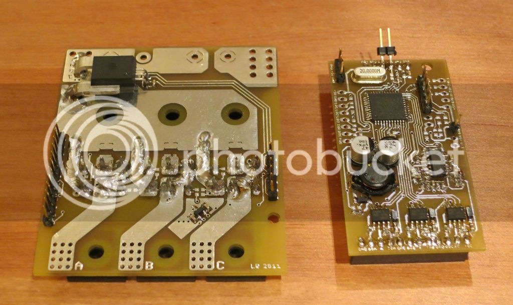
I am now with a more powerful microcontroller (ARM 32 bits 48MHz) than the AVR 8 bits 20MHz of Arduino but when I have the code/algorithms tested, we can port them to AVR/Arduino.

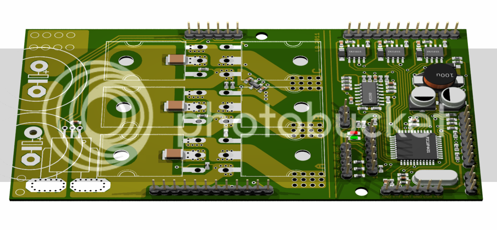
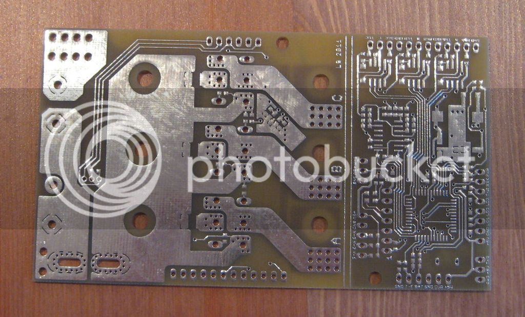
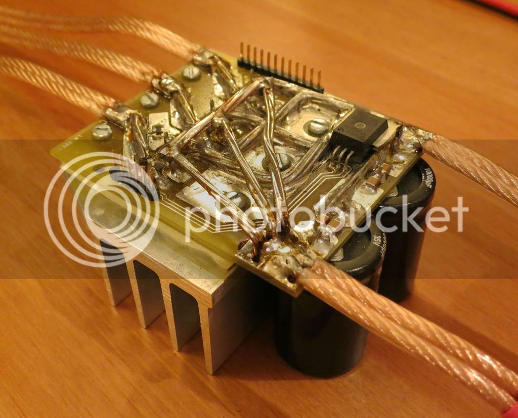
I am trying to take a short cut by using a KU63 controller and just exchange his microcontroller by my own ARM LPC2103 32 bits 48MHz. I need to learn and test the controller.

ram0nb said:
My final goal is to develop a 80V 50A BLDC controller with wifi ap and webserver (or bt) for communications with smartphone to control and monitor my ebike.

Will have a look for the my controller design files in Eagle. Can post those if any interest.
My final goal is to learn and build something I can use. And I will start for something low, like the KU63 controller for 24V. KUxxx controllers are almost the same hardware but they go up to 500W motor and 24/36 and 48V.

For Smart Phones, I will use cheap Bluetooth modules because they work, I used them on my projects like this: Smart Scale

Yes, please share, we can always learn. Thank you.

You can always join this project, maybe following my idea of using KU63 controller and a microcontroller board... together we will get further.
 
I just got my last order from BMSBattery and I got 2 x KU63 24V controller. I am out of time on this days but I plan to continue working on the project. Last time I had problems (short circuits??) on mosfets...
 
Allthough I've no so much time to spend, I'dd like to join the project.
I'm not stuck to Arduino platform. Just started with a Netduino, a Wifi module and .net micro framework to play arround.

Also got a controller over here with the same X8M06-C processor. Any luck with uploading / changing the parameters like on Infineon based controllers? Anyway, I like the idea of swapping the cpu with your own.
 
ram0nb said:
Allthough I've no so much time to spend, I'dd like to join the project.
I'm not stuck to Arduino platform. Just started with a Netduino, a Wifi module and .net micro framework to play arround.
Joining means for now to use KU63/93/123 controller(s) and developing and/or testing firmware.

KU63 costs only $15 here: http://www.bmsbattery.com/controller/188-hall-sensorsensorless-250watts-brushless-hub-motor-controller.html

ram0nb said:
Also got a controller over here with the same X8M06-C processor. Any luck with uploading / changing the parameters like on Infineon based controllers? Anyway, I like the idea of swapping the cpu with your own.
I don't know nothing about X8M06-C processor. The board with ARM microcontroller I use just costs $10 and so I prefer to use it, I know how to use it and it should be up to the task.
 
Just when I think I'm starting to become the local "E-Bike Expert" I find a thread like this and I realize how much of a beginner I really am! Let me just say that while I know almost zero about electrical engineering this is almost EXACTLY what I've been looking for! Ever since I first learned to blink an LED with an Arduino suddenly I'll find myself "mentally reverse engineering" anything with a circuit. But this is one I've been looking for months! I doubt I can add very much to the conversation as it stands other than to say "keep doing what your doing"! but I urge you to consider that there might be a broader demand for such a product if presented right.
I stumbled upon the E-Bike community via a broader search for rural transportation innovations which otherwise involves real-time vehicle location data feeds and other software oriented stuff and I keep asking myself why it should be necessary to have a microprocessor run the motor, another to log data and another on the smart phone. Please let me know if you need a beta tester. Info on my own project can be found here-http://humblehackers.wikispaces.com/The+Flying+Yankee-+A+DIY,+Foldable+E-Bike!
 
carfreemaine said:
Just when I think I'm starting to become the local "E-Bike Expert" I find a thread like this and I realize how much of a beginner I really am! Let me just say that while I know almost zero about electrical engineering this is almost EXACTLY what I've been looking for! Ever since I first learned to blink an LED with an Arduino suddenly I'll find myself "mentally reverse engineering" anything with a circuit. But this is one I've been looking for months! I doubt I can add very much to the conversation as it stands other than to say "keep doing what your doing"! but I urge you to consider that there might be a broader demand for such a product if presented right.
I stumbled upon the E-Bike community via a broader search for rural transportation innovations which otherwise involves real-time vehicle location data feeds and other software oriented stuff and I keep asking myself why it should be necessary to have a microprocessor run the motor, another to log data and another on the smart phone. Please let me know if you need a beta tester. Info on my own project can be found here-http://humblehackers.wikispaces.com/The+Flying+Yankee-+A+DIY,+Foldable+E-Bike!
Hello carfreemaine :)

I must say that I also own foldable bicycles. My top reference is Brompton bicycles but I still don't own any.
I am thinking in start testing my 24V 250W motor and this EBike Smart Controller on one small and foldable bicycle :)

I really think we must OWN our own controller and he must be Smart. I believe the best (simple, cheap, accessible) way to make Smart the controller is to put it communicating to a Smart Phone, which will then be able to route all data to web. Also Smart Phones have the touch screen which are great for the needed interaction with the controller.

Unfortunately I am not having success with my efforts on the controller... seems I am always put it with short circuit when I am trying to energize it... I wish I could get help from another developer...

carfreemaine, if we have the controller technology with us, we can move to other kind of new concepts, like the one I like a lot: One wheel bicycle (with pedals for pedaling). See here a video of one wheel scooter from Ryno Motors:

[youtube]ojv8vIRvf6A[/youtube]
 
I am slowing working on this project. The recent actions were:

- working together with luvxu user. He did already a few commints of the firmware to github.
- testing of the firmware ideas for startup of the motor (without success)
- planning for use the hardware of Open Sensorless BLDC controller.

I found that Open Sensorless BLDC controller hardware is expensive but it should also be much better to use/develop for. KUxxx controllers seems to be optimized for cost and are complex for me to understand, also they can't measure current only the maximum current -- I really want to measure current and voltage.

I plan to assembly by hand the power section on a perfboard and keep a stable interface with control section. Control section should also be assembled by hand on a perfboard but also using the ready available ARM board I used until now.

Pictures from latest hardware of Open Sensorless BLDC controller:
Untitled-2.png


Untitled.jpg


Untitled-1.jpg


Untitled-3.jpg


IMG_0120.jpg
 
I had another idea:

KUxxx controller just misses current sensor. Why not add the sensor current (ACS756SCA) to the input of battery on KUxxx?

ACS756SCA-100B sensor IC on Open Sensorless BLDC controller schematic is in series of the negative of battery. It should very easy to apply the sensor on the negative of battery on KUxxx controller!
 
The motor runs!! :)

But the firmware starts only the motor at a fixed frequency commutations (5ms, measured with my Cute85 motor at start/slow velocity) and at fixed duty-cycle. Here is the video I recorded:

[youtube]9yG4NSVBGEs[/youtube]

The firmware for it is here: https://github.com/casainho/EBike-Smart-Controller/

Here is the main loop:
Code:
int main (void)
{
  /* Initialize the system */
  system_init ();
  //timer0_init ();
  //timer0_set_us (1000000);
  //timer0_start ();
  //enableIRQ ();
  timer2_init ();
  pwm_init ();
  ios_init ();

  update_duty_cycle (250); // 25% duty-cycle

  while (1)
  {
    // Testing the start-up motor
    commutation ();
    delay_us (5000); // 5ms commutations of each step --> ~30ms period, measured on Cute85 slow/start velocity.
  }
}
 
I made some simple but interesting tests.

With 15% duty-cycle and 10ms the motor were running very slow (about 12 RPMs, motor Cute85 for 20'' wheel). But I were using the variable power supply and I could change the power applied to motor by defining the voltage supply.

(Case 1) I found that with a lower voltage, like say 15V, the motor don't turn or vibrates/makes noise/small turns. (Case 2) If I rise slow the voltage it starts to turn up to a velocity which seems to be perfect (but slow due to the 10ms), no noise, no vibrations. But if I brake the motor with the hand, it starts to vibrate/make noise and stops...

(Case 3) Continuing, if I rise the voltage (without braking the motor with my hand) the motor starts vibrating/making noise again but this time rising also the current/power used!!! Then I tried to brake and it stopped to make noise/vibrations but the current still high. I had a bit difficult to brake and stop the motor. I rise again the voltage and keeping brake the motor, until I found I couldn't no more brake it!! it turns with strong power, no vibrations nor noise.
 
I started to document on github wiki the test I made with KU63 controller and Cute85 24V motor. I am also documenting the pin connection between KU63 controller and LPC2103 microcontroller - here:

https://github.com/casainho/EBike-Smart-Controller/wiki
 
Back
Top