Just to make sure we are on the same page...
What
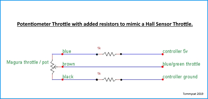
throttle make and model are you using?
What type of
controller throttle control are you using? I.G. Potentiometer type (0-5vdc) or Hall sensor type (.8-3.6vdc)...?
What mode of transportation are you working on?
As far as testing goes... just a friendly reminder to keep an eye on your
current usage draw on the 5vdc rail.
Jumping around between pots and resistors during testing with voltage divider circuits. (power to ground thru resistances...) It's easy to pass the boundaries of what the controller's 5vdc regulated output supply can handle. Which may be as low as 100 mA. (milliamps) To be safe I'd keep it below 20mA.
I like that you're using an old controller for the power source and testing. But an even better/safer idea would be to use a separate power supply such as a USB wall wort. or even battery power (I.G. 3- 1.5vdc batteries in series...) to test with... You can still use the controller hooked up to the throttle output with this testing set-up. But you must connect the grounds (5vdc negative) together.
From your cruise diagram, it appears that you're just switching from one variable pot (throttle) to another that's set to a certain voltage output.
I would concentrate on first getting your throttle to work properly. And then add to that to achieve your cruise voltage. Perhaps using a single switch to bypass a resistor (one of a couple in series) in the ground leg, I think the same results could be had.
That said
caution is required when using such a control. This switch could be inadvertently activated by accident, even with the bike unmanned. The braking system would not automatically turn cruise off. It would have to be manually turned off, without any
automatic releases...
For these reasons I would encourage you to look into a controller that has cruise built in.
Just as an example... my Magic Pie internal controller has cruise that I use constantly and really enjoy.
It has a push button setpoint. Disengages with brakes applied. Disengages when the throttle is moved, or if the button is pushed again.
I've also seen controllers that will engage cruise after the throttle being held in the same position for a set amount of time.
Please answer the questions above... but yes it would seem that you need smaller resistors.
The snippet from "the guide" below may shed some light.
As always you can use a variable pots to "dial in" the resistances needed and then replace them with a set value resistor after measuring what it's set too. Much easier than shuffling resistors in and out.
A posted picture of a hand drawn schematic of your wiring with test points and voltages would be extremely helpful.
") *****************************************************************************************************************************
*****************************************************************************************************************************
Controller...
Provides the regulated 5 vdc input voltage for sensor operation. And receives the variable output voltage from the sensor to determine power output to the motor accordingly. The controller will also lock out motor operation if throttle sensor input is higher than 3.8 vdc (shorted output). Note some throttle manufactures may put a voltage drop resistor between 5 vdc+ and ground for the specific reason of making sure full voltage output stays below the controller lockout voltage. Lower than .4 vdc (open output, error code #2), or somewhere in the middle on power up (stuck throttle), which will automatically reset when the throttle is returned to the full off position. All to prevent unwanted or dangerous operation.
These safeties are certainly welcome but may get in the way of throttle troubleshooting... be aware.
*****************************************************************************************************************************