Rickys Keewee stealth RC bike buildlog

Ricky_nz

10 kW
Joined
Aug 15, 2010
Messages
844
Location
New Zealand
Hi All,

After experimenting with an 300W elation kit and a 1000W rear golden motor with magic controller
I have decided what I like and don't like and this will feed into this new project.

The V2 elation kit suffered several issues:
1) Cranks keep bending (aluminum too weak)
2) early failure of battery just out of warranty :-(
3) freewheel failed
4) Throttle slow ramp step thing is intolerable. (must get round to putting a different throttle on.
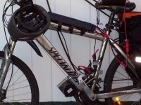
elation.JPG
I still use the elation kit regularly to get to work and it works ok with a 7s2p turnigy 20C pack. much less votage sag.
I have swapped out the freewheel to a sick bike parts one but astill want to do something to the throttle.
This bike is great with its hayes hydro brakes so the new project must have hydro disk brakes. The elation is not too bad for 300w peak 750W but you are always banging through the gears and I have noticed that it does contribute to cluster wear because of the number of gear changes to deal with the very narrow power band.

The golden motor bike I originally run 4 * 18Ah SLA in the frame and it handled ok but it was heave and poor range. V brakes are not ideal for a bike like that. It runs better now i swapped it over to 14s2p 20C 5Ah turnigy ( I use half of the pack for the elation kit and 14s fits the voltage range of the controller. I don't like the heavy hub in the wheel but it is a reliable setup but adjusting v brakes every other week gets old!
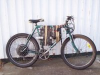
20Kgoflead.JPG
If you are even thinking of lead stop! go no further. you must use Lipo! I brought the lead when the nz doller was dirt but now it better and I have discover hobbyking lipo there is no turning back!


The new project
This project is about a bike that accelerates fast and is reliable.

The drive will be 219 chain on the left to the break disk mount with a chain primary reduction of 2 and secondary of around 8.
It will be LiPo powered approx 1KWh or more if i can afford it.
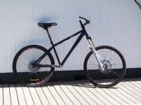
The bike is a keewee stealth dirt jump frame with manitou 200mm suspention forks.newprjbase.JPG
This won't be a fast build.
I'm more into software and electronics so some of the mechanical stuff is net to me but i'll get there.

I'm putting up the build log to keep me motivated to complete the project and to hopefully share ideas etc.
I have just had the first PCBs for my controller come in so I'll post about that shortly

This build will be supervised by Leica the mad oriental cat.
 
Controller Board

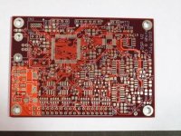
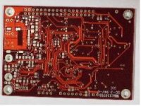
Just arrived:
pcbtop.JPG
pcbbottom.JPG

This board holds a 120MHz 32 bit processor and a dual sampling 12 bit ADC in addition to the controllers on chip ADC.
Nothing like a bit of overkill!
A microsd card socket for data logging and configurations etc.

This card has protection clamping on all IO to help protect it in the event of a plasma event on the power board.

I have started assembling the controller and so far no issues with the PCB which is great considering the NRE costs for a 4 layer board. Its been a few years since I did any major smd assembly so a few of the solder joints are a bit rough but I'm definitely getting better as I go. I will go back and clean up a few of the first ones I think.

I hope to have the basic operating system / flashing LED up on the board by the end of the weekend.
not sure how much I'll get done before the weekend, Work keeps interrupting my projects :-( Pity I need to work to fund my projects.

I have a 12Fet TO-247 power board layout ready to go. Just undergoing final checking.
This is not going to be a cheap controller but that is not the aim.

The software is no problem for me as I write software for 100KVA+ inverters for a living.
I had written some software already for the fixed point maths but I need to make some small alterations as I swapped to a newer processor than the one on my dev board.
 
You are extremely smart to go with TO-247 package FETs. A controller based on 12xTO-247 fets will be stronger than any TO-220 based controller I've seen on this forum.

Will your controller brain board with programmed uController be available for developers to buy and assemble themselves?
 
I am considering making boards/programmed controllers available once I get the basics up and running.
I'm not great at smd assembly though probably get better after I build a few more up.
 
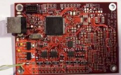
Partly assembled board. Assembled late at night when is was really a bit too tired to be doing it.
part_assembled.JPG
 
Ricky_nz said:
I am considering making boards/programmed controllers available once I get the basics up and running.
I'm not great at smd assembly though probably get better after I build a few more up.


I'm pretty slick with SMT assembly. :) Paste, hot-air station, toaster-oven re-flow, and of course an iron. If you wanna send a boards out with just the programmed chip on it, I will happily assemble a few.
 
Hi,
Could be an option, probably much better then me assembling by hand with my hakko soldering station.
Once I get a bootloader written that should be all thats necessary to put the rest in. The 1.27mm pitch header in the top left corner is JTAG for the LPC so not too hard (non standard connector I know but the standard ARM ones are too big and openocd doesn't support SWD yet) , It has 512kb of flash on chip. not sure if I will use a usb boot loader of put firmware updates on the sd card. This means that to put a bootloader in requires the CPU be soldered down.

Its kind of mad that the processor is cheaper than the ADC but the ADC in the LPC1769 is a bit weak. I went with dual sampling so I could use 2 CT's and calculate the third for the phase currents.

Will probably make decisions about assembly etc once I get the basics up.

I will post a pinout of the control board connector later in case you or anyone else is interested. It should be able to be hooked up to any desired power stage. just add gate drives and MOSFETS. sounds simple but thats usually a big can of worms. The control board has on board regulators so requires a 15V supply. My power board has an onboard switching regulator that can handle up to 100V in to generate this with enough extra power for lights etc. no worries about overloading it causing the 15V gate drive to sag as the micro will be monitoring the 15V rail and will trip the PWM off at the first sign of trouble.

The control board also has hardware trips that will turn off the PWM generation without software intervention of hardware overcurrent.

anyway I better get ready for work.
 
Ricky_nz said:
Hi,
Could be an option, probably much better then me assembling by hand with my hakko soldering station.
Once I get a bootloader written that should be all thats necessary to put the rest in. The 1.27mm pitch header in the top left corner is JTAG for the LPC so not too hard (non standard connector I know but the standard ARM ones are too big and openocd doesn't support SWD yet) , It has 512kb of flash on chip. not sure if I will use a usb boot loader of put firmware updates on the sd card. This means that to put a bootloader in requires the CPU be soldered down.

Its kind of mad that the processor is cheaper than the ADC but the ADC in the LPC1769 is a bit weak. I went with dual sampling so I could use 2 CT's and calculate the third for the phase currents.

Will probably make decisions about assembly etc once I get the basics up.

I will post a pinout of the control board connector later in case you or anyone else is interested. It should be able to be hooked up to any desired power stage. just add gate drives and MOSFETS. sounds simple but thats usually a big can of worms. The control board has on board regulators so requires a 15V supply. My power board has an onboard switching regulator that can handle up to 100V in to generate this with enough extra power for lights etc. no worries about overloading it causing the 15V gate drive to sag as the micro will be monitoring the 15V rail and will trip the PWM off at the first sign of trouble.

The control board also has hardware trips that will turn off the PWM generation without software intervention of hardware overcurrent.

anyway I better get ready for work.


Everything sounds great! I'm loving the double current input ability to know true phase currents. :)

I'm more than happy to help if you need a hand with assembly.
 
Professor%20John%20Frink.gif


geez u guys.........

haha nah sounds good, development in any controller is always good.
 
I know its technical/geeky but its the sort of thing needed to drive motors like AJ's monster rewound turnigy without blowing up. :)

The board above is just the brains of a motor controller.
 
For the other electronics geeks out there heres the pinout of the controller interface to the power electronics stage.
The 3 GPI inputs are connected to the encoder interface and to interrupt pins (for hall sensors) on the micro so should be easy to support any type of BLDC control.
all supplies generates from the supplied 15V
 

Attachments

  • connector.bmp
    332.8 KB · Views: 3,966
AussieJester said:
not sure what the hell it is but if Lukes impressed it must be special...

Ricky has the brains, Luke has the brawns. When both are combined, you have POWER! :)
 
hehe not havin a crack at you ricky_nz.....you obviously know what your doing.......thats just what it looks like to me. I wish i was smart enough to get into electrical engineering at uni....I had to settle for IT instead. Im with kim here....if lukes impressed then it must be a big deal. Even a sensorless controller able to handle 10kw 100% reliably is an advancement on what we have currently. The more people (smart like yourself)we have working towards a solution to a scaleable bulletproof(or bone head proof :wink: ) controller...the better.

Cheers
Rodger
 
Likewise with Luke, if you want assembly work done i can help. I've got access to oven, hot-air and of course Irons. Also have microscope inspection stations. Soldering is half of my day job activities.
 
Hi boostjuice, thanks for the offer.

I'll see what happens once i get the first few boards up and running.
I have 5 boards to start I will build by hand (just a few parts short).
The last 4 will go quicker as I'll not be searching for different parts as i go

First one now ready for initial software tests.
After I get some tests done and some initial software I will have to decide what to do and if the interest is there to build more.
of the first 5 boards I need 2 and a mate at work is interested in one so there should be 2 spare if someone is really keen on playing.
I haven't worked out costs or anything yet.
This all assumes once I get some software going and exercise the board that I find no major issues.

To do real software tests I need to hurry up and get my 12 FET(IRFP4368) power board finalised and ordered but while that coming in I can get the basic software up and running and check all IO, ADC's etc.

Ricky
 
Hi Rodger,
humor is good :).
Those early career decisions do tend to stick you in one direction sometimes before you know enough to know what you want to do.
Lucky the internet is there to provide large amounts of information on areas that you find interesting later as a hobby.

Ricky
 
Hi all,
Just got some simple test code to flash some LED's programmed into flash so its a good start :)

Hopefully over weekend I'll start putting some real code (basics of the operating system) in the board.
[youtube]J5Rr2l7KzGg[/youtube]
 
Hi all.
I've finally made some more progress.
Still not much to see but the LED flashing is now more complex behind the scenes.
I have got http://www.freertos.org/ freeRTOS running and have got the openOCD debugger setup behaving properly.
FreeRTOS is a real time operating system intended to run on microprocessors.

Unless you have a software background it appears as just 3 flashing LEDs but the details behind it are what that matters!
The early one was very simple code with the processor running slow in a loop with delays where as the latest one is created by three different processes running in the operating system using interrupts and the processor running at the full 120MHz!
[youtube]6XmLsp9PKXM[/youtube]

I hope to start bringing up drivers for the different IO devices on the processor over the next few days.

The board is currently drawing about 95mA with the 3 LED's flashing and all comparators & opamps installed. the only power consuming device not fitted is the ADC chip which will use about 40mW so power consumption dosn't look too bad.

I expect the current draw to also go up when I commission the microSD card interface and install a card but it is well within the capabilities of the regulator which runs warm currently but not hot.

Ricky
 
Yes! scope capture showing correct configuration of FreeRTOS clock. LED being flashed at 100ms on / 100ms off as requested.

Now thats confirmed I can move on to real stuff like ADC's and PWMs
 
Just curious what language for the firmware or environment? C, vx, etc?
Cool idea, very similar hw to arm type wifi router, come to think of it.... How many gpio pins are you using for gate driver and hall detection? Maybe we could slave some of the wifi routers to use as brain prebuilt and repurposed?

-Mike
 
This is really fantastic stuff Ricky! I'm loving seeing the rapid progress. :)
 
Hi Mike,
I'm writing in a combination of C and C++ using GCC so standard GNU tools. I use a olimex USB debugger (FTDI chip based) with openocd for debugging so again cheep software development.

The LPC1769 has the advantage over a generic ARM that is setup for networking in that it provides lots of useful features in hardware.
The LPC1769 has a dedicated motor control PWM block to provide the 6 PWM outputs.
It supports interrupts from many of the IO pins so the hall inputs are hooked up to these.
Since the PWM block is hardware on chip it runs by itself and can be stopped within the current PWM cycle immediatly if a hardware overcurrent is detected etc.

The LPC1769 also has on chip ADC converters which I will use for throttle/brake/temperature etc whereas I guess most ARM processors on Wifi routers probably don't have although I have added a high performance ADC because the one on the LPC is not really good enough for the high speed operation I'm aming for. Tacking on wires to a router to interface with an ADC could be fiddly although maybe a high speed SPI one could be used.

For simpler operating modes like trapesium with hall effect devices I guess you could probably bit bang the PWM on GPIO fast enough but I'm intending to do full vector control and support sensorless and sinewave modes so I will need all the processor speed I can get just to do the maths.
Its tough to drive 1000Hz motors (Turnigy 80-100) with sinewave. Current control loops running at or near the PWM frequency!

I'm not sure the cost of my board yet, I should work it out as I don't think it will be too bad and certainly easier than tacking on a lot of extra HW onto a router.
The cpu as about $12.50 US in single quantities which is cheep for all that performance! The ADC is a little bit dearer though but in some applications unnecessary as the CPUs ADC can be used. The only other parts are some common compartors and a couple of average opamps and a handfull of passives and a couple of transistors.
 
Trignometric lookup tables are your friend. :) Just keep in mind cos is a phase shift of sin, tan is a combination of sin and cos and everything else is based on that. In essence, you only have to have one sin lookup table.
 
Back
Top