Rickys Keewee stealth RC bike buildlog

ev_nred said:
epic!!! nice job man!!! :mrgreen:
sorry for asking a stupid question, any idea on if and when your going to be selling these monsters? if so how much well u be selling them for? thanks

I Will probably sell a small number at some point. They will be hand built initially.

I need to get the power board up and running. I have given myself a target of hall effect based trapesium motor drive running by the end of the year provided I get the power board ordered in the next few days. I will road test this on my GM 1000W hub motor at 57V or more if I order more lipo batteries.

Before I could sell any I need to ensure the design not only works but works for several boards and is reliable which should happen early next year.

I will keep working on software after basic functionality works. The software in the control board is user update able. I just need to finish the bootloader and It should be a matter of plug into a usb port to update software.

My plan is to start with a simple Trapezoidal hall sensor based drive and then as a separate operating mode develop full vector control including a decent sensor less one that works with sinewaves. I will probably keep some of the software proprietary but I can also provide a basic runnable set of sourcecode based on freertos that configures all the IO etc that can be used for others to implement anything they want, I would provide information as necessary.

I have not worked the cost out yet. I've been too busy getting the rest ready. I will probably start working out costs when I order another batch of parts after the first power board works but there is no way this could compete with the e-crazyman chinese controllers on price but it will provide a lot more protection and features :D .
As I would be buying limited numbers of parts and some of the parts are more specialised for example the shunt in the ecrazyman is probably a few cents where as the CT's in this are more like $7 from memory. My first batch of MOSFETS was painfully expensive. Hopefully If I buy more it would come down.

There could be another option for those that like building to buy bare PCBs of the power stage and a programmed micro board. That would allow a lot of customisation.

I can see NZ post taking a premium to ship it overseas :roll:, I might have to investigate the options there.

Edit:
I've got to think about how to test the power electronics to full power without having the sensor less algorithm that I need for the 80-100 initially. I have a few ideas and should be able to drive it to full current short periods or time. The GM hub should be a cake walk for this controller to not only run but barbecue :lol: so I will have to get the turnigy going fairly quickly and maybe run 2 motors and controllers back to back so I can circulate power. We may have 240V mains here but you can still only pull 2 or 3KW out an outlet so many tests will have to rely on batteries.
 
My PCB checking has payed off :lol:

Just found I had used the wide package for the gate drives where as they are a mento to be narrow soic-14 :oops:

The fix is relatively minor as the pinout is correct, just the spacing between the rows of pins.
Just one trace can't co under the device anymore and shunt the pull down resistors around and it passes DRC again :)

This could have been hacked on the board but would have been one ugly mod :lol:
 
Ricky_nz said:
I Will probably sell a small number at some point. They will be hand built initially.

Well...i don't understand 99% of what is said in this thread WaY above my head but i did understand the above ^^^
if theres a list put me on it please i would definitely like to try your u-beaut controller out Ricky_NZ

best of luck with the continued design/build work mate i shall keep following along possibly at some
point it will "dumb down" to my retarded level of understanding and i can offer some form of input haha..

KiM
 
AussieJester said:
Ricky_nz said:
I Will probably sell a small number at some point. They will be hand built initially.

Well...i don't understand 99% of what is said in this thread WaY above my head but i did understand the above ^^^
if theres a list put me on it please i would definitely like to try your u-beaut controller out Ricky_NZ

best of luck with the continued design/build work mate i shall keep following along possibly at some
point it will "dumb down" to my retarded level of understanding and i can offer some form of input haha..

KiM

Looks like you started the list :). no problem with that.
It would be great to see one of these controllers on one of your creations at some point.

Once I get the first prototype running I'll need to decide on the interest level so I can decide how many more to build and work out costs so a list of interested people is good.
Also puts you in the queue when I start building them as it will depend on my available time.

I'll try remember to put up simplified summaries up so you can follow the progress without knowing all the gritty details and don't worry, things will definitely dumb down as I hit the mechanical part :lol: ( I specialise in electronics and embedded software).
If it says too complex for too long feel free to prod me to put up a summary :)

I will also have to make some form of user documentation for it.

Hopefully I don't end up with any entertaining explosion videos as I test and debug this controller :lol: .
I will keep the camera rolling at key moments just in case.
I want this controller to be electric and not internal combustion :lol:


When I started the thread I wanted to keep the details of the controller in bike together so put it in non-hub but maybe it should have been in technical.
 
The checking is going well. No more footprint issues have shown up.
The library parts look good so far.
Not so happy about my solder mask cutouts that allow for beef up critical tracks yet. Just need a bit of cleaning up to look nice. They are functional but could look nicer :).
I have started doing test Gerber plots to check that I have the settings right and so far it looks ok in GerbMagic.

One crucial check:
100_2831_small.JPG
Yes it does line up with the control board when printed 1:1 :D.
The top right corner is fine, its just the angle of the photo
Guess that also means my tired Laserjet 5L is still managing to drag the paper through evenly.
It has an issue where the paper pickup pads grab all paper in the in slot when there is about <20 sheets left and trys to feed the lot through at once. I really need to buy a new printer, 3 pages per minute doesn't cut it any more. I have had a lot of use out of this printer though, brought it at the end of 1996 and its still running.
I won't buy a vertical feed laser again though due the the feed issues. Its 1MB of memory isn't ideal anymore as it was always marginal at 600dpi.
 
It took a bit longer than expected to get the PCB ready to order. But since nothing will happen if I order it now I will order it Monday to allow for final checking of the gerbers files on Sunday.

I found a minor issue in how I handled the enable signal to turn on the main switching converter.
While solving that minor issue I decided to see if I could implement the shutdown after X time feature suggested in another thread (thanks). Turns out with my fix It becomes really easy :D. It will mean that to enable the feature you must sacrifice one of the general purpose outputs on the control connector so I will not put the link on the board so if the feature is not needed the output pin can be used for some other purpose.

It is a simple matter of adding a wire link between 2 pins of the control connector.
The start switch must then be momentary which isn't ideal but that can be managed. I have some ideas that won't require PCB changes to cope with normal switches.

This works because the enable pin must be pulled low to turn on the converter.
Once its on the micro can hold the pin low until it wants to turn off. This will reduce the idle power of the whole motor drive to micro amps :D which should provide a measure of protection to any unprotected batteries. This is especially important with a controller like this where it is impracticable for a BMS to disconnect the batteries.


The LM5116 switching converter draws 10uA in standby and if I add in the power consumed by the DC bus voltage sense resistors the total standby current is about 260 micro amps :D.

Edit:
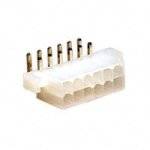
While checking the PCB I had a good look at the" Molex Mini-Fit Jr" connectors I'm using for the control and motor interface connectors and with the larger size crimps installed they look like a really good connector to use for balance taps where a reasonable of current is required to pass. The PCB pins are 1.4mm diameter. They have a latch to prevent accidental disconnection.

39-01-2120_sml.jpg
39-29-1128_sml.jpg
They are reasonable small and are a much better connector than the JST-XH connectors.
 
For those interested in techo details is a crude BOM output to give you some idea of the parts I've chosen.
Not all caps will be fitted if testing proves some are unnecessary as there is a cost consideration.
I have specified some nice MLCC caps but they are quite pricey :lol:.
I guess its the price you pay for high power.
[pre]Comment Description Designator Footprint LibRef Quantity
"680uF/100V" "CAP 680UF 100V ELECT FC RADIAL EEU-FC2A681 " "C1, C2, C3, C4" "CAPPR7.5-16x25" "Cap Pol3" "4"
"100n" "Capacitor" "C5, C10, C12, C20, C27, C29, C30, C31, C32, C33, C38, C39, C41" "CR2012-0805" "Cap" "13"
"100n" "B32620A5104, B32621A5104J, Capacitor" "C6, C7, C8, C24, C25, C35, C36" "RAD-0.4" "Cap" "7"
"1uF" "1uF Y5V +80/-20% MCCA000305, Capacitor" "C9, C13" "CC2012-0805" "Cap" "2"
"10uF" "10uF/20V 1206 / Case A T491A106M020AT" "C11, C28, C40, C63, C64, C65" "TC3216-1206" "Cap Pol3" "6"
"10uF/100V" "RUBYCON 100YXF10M6.3X11" "C14" "CAPPR2.5-6.3x11" "Cap Pol3" "1"
"10uF/25V" "Polarized Capacitor (Surface Mount)" "C15, C16" "1812" "Cap Pol3" "2"
"100nF" "Capacitor" "C17" "3216[1206]" "Cap" "1"
"1nF" "Capacitor" "C18" "CR2012-0805" "Cap" "1"
"33pF" "Capacitor" "C19" "CR2012-0805" "Cap" "1"
"10n" "Capacitor" "C21, C34" "CR2012-0805" "Cap" "2"
"390pF" "Capacitor" "C22" "CR2012-0805" "Cap" "1"
"9nF" "Capacitor" "C23" "CR2012-0805" "Cap" "1"
"1uF 100V" "18121C105KAT2A" "C26, C37, C42, C43, C44, C45, C46, C47, C48, C49, C50, C51, C52, C53, C54, C55, C56" "CD4532-1812" "Cap" "17"
"10n 100V" "" "C57, C58, C59, C60, C61, C62" "CC3216-1206" "Cap" "6"
"conn_36" "" "CN1" "HDR2X18" "conn_36" "1"
"ES1D" "Default Diode" "D1, D2, D3, D4" "SMA" "Diode" "4"
"MMSZ5226BS-7-F" "DIODE ZENER 3.3V 200MW SOD-323 MMSZ5226BS-7-F" "D5, D6" "SOD323" "D Zener" "2"
"Header 12" "Header, 12-Pin" "IO" "MOLEX 0039291128" "Header 12" "1"
"P0751.223NLT" "P0751.223NLT inductor Pulse engineering" "L1" "SMD_INDUCTOR" "Inductor" "1"
"Header 6" "Header, 6-Pin Mini-Fit Jr 5569 Molex 0039291068 Male pins RA header PCB flange mount" "Motor" "MOLEX 3x2 0039291068" "Header 6" "1"
"IRFP4368" "N-Channel Power MOSFET" "Q1, Q2, Q5, Q6, Q7, Q8, Q9, Q10, Q11, Q12, Q13, Q14" "TO-247 - bottom face to PCB" "NMOS-2" "12"
"IRF7494" "HEXFET N-Channel Power MOSFET" "Q3, Q4" "SO-G8" "IRF7494" "2"
"BSS86" "BSS86" "Q15, Q16" "SOT89" "BSS86" "2"
"PBHV9115T" "PNP Bipolar Transistor" "Q17" "SOT-23B" "PNP" "1"
"330K" "330K/200V 1206" "R1" "3216[1206]" "RES" "1"
"10K" "10K 0805, Resistor" "R2, R36" "2012[0805]" "RES" "2"
"10R" "Resistor" "R3, R8, R9, R18, R19, R24, R25, R26, R29, R30, R38, R43, R44, R54, R55" "2012[0805]" "RES" "15"
"0R" "Resistor" "R4, R7, R13, R45" "2012[0805]" "RES" "4"
"110K" "Resistor" "R5" "2012[0805]" "RES" "1"
"7K32" "Resistor" "R6" "2012[0805]" "RES" "1"
"100K" "Resistor" "R10" "3216[1206]" "RES" "1"
"1M" "Resistor" "R11" "2012[0805]" "RES" "1"
"13k7" "Resistor" "R12" "2012[0805]" "RES" "1"
"3K01" "Resistor" "R14" "2012[0805]" "RES" "1"
"1k21" "Resistor" "R15" "2012[0805]" "RES" "1"
"1K" "Resistor" "R16, R17, R22, R27, R28, R37, R51, R52" "2012[0805]" "Res" "8"
"0.03R" "Resistor" "R20" "3216[1206]" "RES" "1"
"19K1" "Resistor" "R21" "2012[0805]" "RES" "1"
"287K" "Resistor" "R23" "2012[0805]" "RES" "1"
"2K2" "Resistor" "R31, R32, R33, R39, R40, R41, R42" "2012[0805]" "RES" "7"
"100K" "Resistor" "R34, R46, R57, R59" "2012[0805]" "RES" "4"
"NTC" "Resistor" "R35" "RAD-0.1" "RES" "1"
"100R" "Resistor" "R53, R56" "2012[0805]" "RES" "2"
"47K" "Resistor" "R58, R60" "2012[0805]" "RES" "2"
"0R" "Resistor" "R61" "3216[1206]" "RES" "1"
"LM5116" "LM5116 Wide range synchronous buck controller" "U1" "TSSOP20EP" "LM5116" "1"
"IRS21864" "" "U2, U4, U6" "SO-G14/G3" "IRS21864" "3"
"ACS758xCB-200" "" "U3, U5" "CB (Allegro DCCT)" "ACS754xCB-150" "2"[/pre]
 
Awesome!! I don't know how I missed this!
I think it's because you hid the coolest controller build thread to date with a build thread. 8)

keep up the good work!

What are you using for layout?
 
grindz145 said:
Awesome!! I don't know how I missed this!
I think it's because you hid the coolest controller build thread to date with a build thread. 8)
Yep. Started a build thread but so far there has been more controller dev than building of the bike :lol:.
I wanted to keep them together but maybe it should have been in the tech section.
This controller is not non-hub specific :lol: it could surly cook a few hub motors if it runs properly.
I think the controller is the bigger part by far but the mechanicals will be the slow part for me.

grindz145 said:
What are you using for layout?
Altium Designer
 
I knew that automatic BOM export looked familiar :mrgreen:

I started using Altium not too long ago for work. It owns.
 
Yes grindz145 it is a good program.

Here is the top overlay without the rest of the board. This one from Gerb Magic. Looks like the gerber files are making sense :D.
This is only the second PCB I have had to send away to be made. I use to make double sided boards at home but now it is impossible to do for many designs such as this one. 4 Layer PTH is much better than some home made board.
The only problem is the non recoverable expense which can be wasted if I mess up.
This is making me a bit cautious of sending it off but I believe I have done sufficient checking. Its been a couple of weeks since the last major change to the board and my checklist is looking good :)

trop_overlay.GIF
I have just fixed the overlapping designator in the above.
Now I need to make sure I can create NcDrill and possible route files to handle the slots in the CT footprint.
 
PCB gerber plot output files and drill files are complete and checked.
Since no more issues that I can spot I'm ready to order finally :D .

I hope I haven't messed anything major up because it would be an expensive waste.

Ok, I'm going for 12 day turn around so hopefully I have it in time for the Christmas break.

Fireworks for Christmas is a possibility* :lol: if the board arrives in time as I have enough parts to build up one board completely and enough parts for a second without MOSFETS.
I do have a few spare MOSFETS for testing but not a second 12 yet.
I better order some more as this project is starting to become real :)

*I really do hope to avoid any fireworks and end up with a working board though
 
The deed is done.
My bank account is significantly lighter now.
140um copper for outer layers and 102um for the internal layers (4 ounce and 3 ounce respectively)

Now the hard part begins...

Waiting :roll:

I hate spending a chunk of cash and then having to wait for the goods :(
Oh well, still a few parts to order and then its back onto the software until the boards arrive.

Hopefully I haven't done anything wrong or left anything out that they need to contact me that would cause a delay. I really want to get this thing producing current and lots of it :twisted:
 
Just ordered enough of the critical parts to allow me to build up 2 75V versions in addition to one 100V version I already have most the parts for.

IRFP4368 and the nice SMD caps for the DC bus.

It sucks buying MOSFETS in small quantities but not as much as buying Locally (which is why I didn't).

In small quantities digikey is 1/3 price of farnell :) still very expensive but when you need parts for prototypes you got to pay.

All prices below in NZ dollars for IRFP4368
from http://www.farnell.co.nz (element14 wtf strange name change?)
1 - 24 $33.80
25 - 99 $24.16
100 - 249 $18.78
250+ $15.08
farnell prices always have to have 15%GST added on to the prices above!

from digikey
1 11.37000 11.37
10 10.23100 102.31
100 8.41200 841.20

Once you spend over $125 digikey ships it for free to NZ.
You just have to keep it below the import level where they charge you 15% GST. it use to be just under NZ$400 but its dropped a bit now since GST went up from 12.5%. They add shipping + possible GST to the item cost and if it is over X$ you have to pay.

Admittedly RS components are closer to the digikey price but they lost one of my orders recently so I don't trust them :(.
You really have to shop around as the cheapest for one part might not be for the next.

I can see once I'm out the prototype stage I will have to talk to the local IRF rep to see if I can access a better price. I'm sure the hardware guys at work can put me in touch. Its been a 5 or 6 Years since I talked to hardware sales reps at a previous job. They probably won't want to talk until very large quantities though.
 
Great work Ricky,Grindz is right, your controller build would be better suited in the tech section, but when you
get this thing going, word will spread like wildfire.

I don't know if your design locks you into certain FETs but Methods is selling some 4115's for pretty cheap. Come to think of it, I think you went with a much more robust FET package as Luke stated.

I would like to grab a controller board if you decide to make a small batch, put me on the list if you will..
 
etard said:
Great work Ricky,Grindz is right, your controller build would be better suited in the tech section, but when you
get this thing going, word will spread like wildfire.

If one of the mods sees this they can feel free to move this thread to the technical section where it technically belongs. :D
I would then create one for the bike separate from the controller but at this moment the thread is 90% controller.


etard said:
I don't know if your design locks you into certain FETs but Methods is selling some 4115's for pretty cheap. Come to think of it, I think you went with a much more robust FET package as Luke stated.
My current power board is specific to TO-247 mosfets.
I will do initial testing with IRFP4368 (75V) and IRFP4468 (100V).

IRFP4368 VDSS 75V RDS(on) typ. 1.46mΩ max. 1.85mΩ ID (Silicon Limited) 350A ID (Package Limited) 195A
IRFP4468 VDSS 100V RDS(on) typ. 2.0mΩ max. 2.6mΩ ID (Silicon Limited) 290A ID (Package Limited) 195A
These are just the datasheet flashey numbers at the top so don't take them too seriously.
I'm running 2 in parallel for a 12FET design.

I decided against a dual footprint and the board layout would make bolting a to-220 device to a heatsink very difficult.

etard said:
I would like to grab a controller board if you decide to make a small batch, put me on the list if you will..
I imagine that I will be in a position to perhaps offer somthng early next year although it depends on progress.

It would also depend on what is needed software wise. I think a good target is having a basic hall sensor based application running before letting control boards loose and then providing software updated to all the nice sensorless stuff as its developed.
 
Just got a few comments back from http://www.pcbcart.com about the layout which I have now fixed up.

Due to my lack of familiarity with laying out boards with thick copper I had some of the overlay crossing between being on top of copper and not which they say will not be very clear so I have fixed a few parts up where it matters.
I also forgot to set one of the clearance rules so I had a couple of clearances that were too small <9mil. They would have been ok on a normal copper thickness board but not on 4 ounce :oops: . Oh well since this is only my second board with an actual silkscreen and my first with thick copper i'll put it down to learning.

Hopefully they don't find any other issues.

edit:
I had set the rule to 0.2mm as on their site but obviously they can't manage that with 3 and 4 ounce copper. They suggested 9mil minimum clearance so I went to 10mil as a minimum clearance and after a bit of shunting parts around it passed DRC again.
9 mil = 0.2286 millimeters so off by 0.0286mm. oh well fixed now.
 
I've got confirmation of target ship date of 4 December but if PCB cart is as quick as last time I may have the board in my hands by then.
Either way the excitement is rising :lol: so time to start gathering the test setup together.

To simulate the inductance of a motor winding for test purposes I will use an inductor.
This ensures that I don't need too much software running and that there is no way I can damage either a motors windings of magnets.

My measurements of the 80-100 180Kv show:
13uH - 27uH rotor position dependant
12mR
All measurements across 2 phases of the delta connected motor.

A 27uH 200A inductor should be reasonable to create as a air cored inductor.
This will allow me to test/thrash the power electronics without risking a motor :twisted: .
I will have to keep the inductor situated so that stray fields don't upset any measurements etc.

Some rough calculations suggest around 20turns depending on size etc.. I will have to find some beefy wire to wind some now.

The large change in inductance based on rotor position combined with the noticeable cogging suggests there is sufficient saliency to allow good sensor-less operation later :D
 
More parts arrive...
1uF 100V ceramic SMD capacitors for DC Bus
680uF 105deg 100V caps for DC bus.
View attachment 1


More heatshrink and another turnigy power meter from hobbyking.
The snail mail finally got here one that one. A bit slower than usual, must be the time of the year but not worth ems for heatshrink :lol: .


MOSFET Porn :D
14 x IRFB4468 100V
26 x IRFB4368 75V
enough for 1 x 100V controller and 2 x 75V controllers plus a few spares for testing.
 

Attachments

  • fets-small_100_2835.JPG
    fets-small_100_2835.JPG
    15.3 KB · Views: 2,351
Hi all,
I have decided to move any future controller development into its own thread after a few suggestions.
The new controller development thread resides at
http://endless-sphere.com/forums/viewtopic.php?f=2&t=23205

This thread will remain for updates about the bike/mechanical parts as I still plan for this to be myu first bike that won't require any form of tape tu function :lol:
 
Not much been going on with the bike as I have been too busy with the controller, see other thread but I now have an Avid elixer R 2010 brake for the back.

They are on special and at chain reaction cycles and I was buying one for my other bike so I decided to buy one for this bike too since it already has an Eelixer R on the front. The only problem is that the one on special was the 203mm version and by the time I push the disc outward at least 10mm to make more room for the sprocket I think I need to use a smaller disc. I happen to have a 160mm disc already ( several actually from upgrading my other bike) and the calliper adapters although the caliper adaptors may be replaced with something custom to move the caliper outward by the required amount anyway.

I have measured the new calliper and it is 15mm from the disc to the widest part of the caliper so I might just be able to make everything fit although clearances will be tight. the cart sprocket must be inboard of the disc mounting surface of the hub and the disc must move outward at least 10mm.
I think I will have to some how do a bit of a mock-up to check for clearances etc. At least this caliper has a banjo so I can adjust the hose exit angle. Should probably do a nice drawing with all the key measurements to make sure.

Anyone got any ideas on how to detect brake activation so that regen braking can be activated before the hydraulics come in too hard.
I was thinking a a hall effect sensor and magnet in the leaver as the avid elixer R offer good modulation so maybe regen can come in before the brakes grab too hard.

Yes that does mean I'm planning regen so no feewheel on the Turnigy 80-100 :D. No freewheels / one way bearings to break.
I will put a zero torque ( low current option for pedalling home on the last remaining energy in the battery as it doesn't take much current to cancel the motors cogging). Just the low voltage cut needs to be high enough to leave enough for a reasonable amount of zero torque motor operation with a lower cut threshold for complete shutdown.
I will also look at an easy way to release the drive from the chain in the event of complete failure.
Since my controller has a lot of protections hopefully It can protect itself from most adverse conditions and avoid failures that could lock the rear wheel.
 
I think a hall effect is probably the best way to go. The little reed switches they use in motorcycles are prone to failure and would be hard to retrofit. Theres nothing really off the shelf that I know about thats decent quality (all chinese garbage).
 
grindz145 said:
I think a hall effect is probably the best way to go. The little reed switches they use in motorcycles are prone to failure and would be hard to retrofit. Theres nothing really off the shelf that I know about thats decent quality (all chinese garbage).
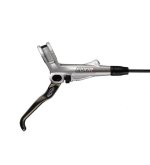
I will have to have a look to see if I can hide a magnet and hall sensor on the brake leaver, its quite compact. I actually want a linear control of the regen so more leaver movment -> more regen brakeing so the hall sensor would need to be a linear one like used on throttles.
I did wonder about a preasure sensor but hall effect is probably simpler if I can hide it.

It might be a challenge looking at the lever below.
elixer-r-leaver.jpg
 
Ricky,
You might want to look into getting a "Top Hat" adapter for the disk brake clearance issues:

http://cgi.ebay.com/Top-Hat-Sprocket-Adapter-Disc-Brake-Motorized-Bike-/110635861240?pt=Cycling_Parts_Accessories&hash=item19c26944f8#ht_1087wt_1139

I tried to make my own and now I feel I shoulda just went with this. I'm not sure if the bolt circle will fit a #219 sprocket, but if it's for a kart, seems like it should. I think I have even seen the guy selling them on ES too.

Those Elixirs are soo badass, I wish I had the money to pick some up. :x

Concerning the regen issue, maybe you can program your controller to hit regen when the throttle is let off completely? What would be truly slick is a little lever ON your brake lever, so that by pulling the brake you first engage the regen lever, then when you need more braking you just pull harder and engage the hydros. Man, sometimes I amaze myself! I should patent this and just sell levers to folks so they can attach the regen lever to whatever brakes they have instead of working with these chinese garbage brakes.
 
etard said:
Ricky,
You might want to look into getting a "Top Hat" adapter for the disk brake clearance issues:

http://cgi.ebay.com/Top-Hat-Sprocket-Adapter-Disc-Brake-Motorized-Bike-/110635861240?pt=Cycling_Parts_Accessories&hash=item19c26944f8#ht_1087wt_1139

I tried to make my own and now I feel I should just went with this. I'm not sure if the bolt circle will fit a #219 sprocket, but if it's for a kart, seems like it should. I think I have even seen the guy selling them on ES too.
Thanks for the link, I will need to get the dimensions and have a look but from a quick look I think the diameter of the part where the sprocket bolts might be a bit small for the kart sprocket. If usable they would definitely save a bit of work. I had considered paying a local engineer to make me one that is just right but that would cost more than the one you linked. I'm not sure about their offsets yet, but definitely worth looking at to see if they can be used or adapted.
Since I don't have access to a lathe I need to buy / get someone to make a tophat of some sort that works with Kart sprockets since the drive train is one place on a bike where tape cannot be used :lol:
Actually I'm trying to make this my first electric bike without visible tape on it.
etard said:
Those Elixirs are soo badass, I wish I had the money to pick some up. :x
They are probably a bit overkill but I could tell they were better the moment I road the bike with them on, they seem a lot more controllable than my old hayes HFX9s. I don't know how they compare to Avids juicy brakes. I wonder if the price difference was really worth it but I do value being able to stop safely very highly.

etard said:
Concerning the regen issue, maybe you can program your controller to hit regen when the throttle is let off completely? What would be truly slick is a little lever ON your brake lever, so that by pulling the brake you first engage the regen lever, then when you need more braking you just pull harder and engage the hydros. Man, sometimes I amaze myself! I should patent this and just sell levers to folks so they can attach the regen lever to whatever brakes they have instead of working with these chinese garbage brakes.
Yes using the throttle is some way would be good, I thought about using the throttle to provide a small amount of regen to mimic engine braking and the brake for proportional control of a much bigger braking effort.
I'm not sure I would want fully releasing the throttle to be hard braking as signaling to turn right requires letting go of the throttle and in stead of coasting up to an intersection full regen might be a bit hairy, especially with one hand on the handle bars :lol:
I'm still working on the motor control part of the controller but when thats done It will be nice to have figured out what I want the braking etc to behave like and throttle response etc.

Figure out how to make a replacement leaver for the common brake brands that works similar to how you describe and you would have a winner :).
I never bothered with those lightweight chinese cutoff switches on my older vbrake bike, I felt safer with the shimano leavers and a separate cutofff switch.
 
Back
Top