Rickys Keewee stealth RC bike buildlog

Another option for getting brake lever operated proportional regen might be to look at fitting a simple force sensor to the lever. I've often looked at these: http://www.sparkfun.com/categories/143 and thought that they could be adapted for small range of motion, force proportional, controls. I looked at using one a while ago for measuring chain tension, via a dérailleur-like tension arm.

Jeremy
 
FWIW, there are some controllers around that use "Demand-Speed" control, so that if you lower the throttle input it automatically begins proportional braking. The 36V EVAssemble controller Yopappamon sent me is like that (except that I haven't yet got it working as regen braking so that it actually loads the motor enough to slow the bike, only the wheel when off the ground). http://www.endless-sphere.com/forums/viewtopic.php?f=4&t=21830&start=0

I sort of like that kind of braking, in that it means I can easily control the speed with just one control, but I also don't like it in that I have to hold to a specific throttle position for a specific speed and can't coast. If it could just do this kind of braking only when the ebrake switch is engaged, then I'd be happy enough. I'd just put a small contact or button near the throttle or on a brake lever to activate the ebrake, and *then* the throttle would slow me down proportionally to how much I push it (or let it off).

But having an "ebrake layer" to the regular brake levers would be perfect; something that activates and proportionally controls the braking effect without activating the mechanical brakes, like the strain sensor. Problem is, most controllers only have an on/off brake input, and no control of them at all beyond that, which kinda sucks. Only controllers like yours that can have this put in from the ground up will really work with such levers.
 
Jeremy Harris said:
Another option for getting brake lever operated proportional regen might be to look at fitting a simple force sensor to the lever. I've often looked at these: http://www.sparkfun.com/categories/143 and thought that they could be adapted for small range of motion, force proportional, controls. I looked at using one a while ago for measuring chain tension, via a dérailleur-like tension arm.
Interesting. Not sure they would achieve exactly what I want in that I would really like to have the system start using regen before the brakes activate much and in that area there is very little force on the brake leaver so I imagine any sensor would have to be incredibly sensitive.
Might add a few to my next order from sparkfun just to play with though :).

amberwolf said:
FWIW, there are some controllers around that use "Demand-Speed" control, so that if you lower the throttle input it automatically begins proportional braking. The 36V EVAssemble controller Yopappamon sent me is like that (except that I haven't yet got it working as regen braking so that it actually loads the motor enough to slow the bike, only the wheel when off the ground). http://www.endless-sphere.com/forums/viewtopic.php?f=4&t=21830&start=0
I imagine my thought about mimic engine braking would be a little like this. It is a bit hard to make comparisons to many controllers as the behaviours of the throttle should be different with my controller anyway.
Mine will be torque based rather an speed which may effect how the throttle feels. I would prefer that the throttle has limited control over the brake but if I do it right it should be configurable to allow playing around with different options. Probably a bit of a dead band between +ve torque(acceleration) and -ve torque(braking). The dead band would make throttle position less critical.

I must remember to put in some code to stop the -ve torque when the motor speed reaches zero otherwise the results might be pretty funny.
amberwolf said:
I sort of like that kind of braking, in that it means I can easily control the speed with just one control, but I also don't like it in that I have to hold to a specific throttle position for a specific speed and can't coast. If it could just do this kind of braking only when the ebrake switch is engaged, then I'd be happy enough. I'd just put a small contact or button near the throttle or on a brake lever to activate the ebrake, and *then* the throttle would slow me down proportionally to how much I push it (or let it off).
Sounds like a usable scheme for if the only available brake sensor is a switch and wouldn't be hard to implement in the software.
amberwolf said:
But having an "ebrake layer" to the regular brake levers would be perfect; something that activates and proportionally controls the braking effect without activating the mechanical brakes, like the strain sensor. Problem is, most controllers only have an on/off brake input, and no control of them at all beyond that, which kinda sucks. Only controllers like yours that can have this put in from the ground up will really work with such levers.
I would definitly prefer the majority of the braking to come from the brake leaver, its more natural but combines with some small amount of configurable 'engine braking' from the throttle position would probably be my preferred setup.

I guess the one problem with my controller supporting linear control of the regen is just the lack of ready made brake leavers. I'm sure I can come up with something. Probably hall sensor based to start with. It would be very easy to do a linear pickup off cable actuated brakes with a variable resistor but I really want to use hydraulic ones.
I guess another option is to find a pressure sensor but that would require finding hose fittings and hacking into the hose and re bleeding them etc. Still might not sense too much for small leaver actuations though.


Thanks for the input. I need to nail down a few requirements like above so I can get that part of the software written soon.
 
Hi all,

I've just been playing with a hall sensor and some 3mm long, 3mm diameter magnets to see how well they will work for proportional control of regen when mounted on a brake leaver.
Unfortunately the parts that digikey had in stock when I placed an order were SOT-23 so I had to mount it on a scrap of prototyping board first.
The sensor is the A1302KLHLT-T. The 1301 may have been a better choice as it has more sensitivity.
People selling magnets on action sites like trademe or ebay etc don't have any real information on the magnets they supply so it was really pick a sensor and get some magnets and have a play.

The results so far:
a) The field / end of magnet must line up with the sensor pretty accurately for maximum range.
b) Not a lot of range. >10mm doesn't report much (can sense magnet at 20mm if perfectly aligned but only just (<10mV). The best operation seems to be in the 0 - 10mm range.
Seemed to get about 20mV change at around 10mm if well aligned. Best performance seems to be in the <6mm area.

I have looked at my brake leaver and this looks like I can make it work.
The sensor and the magnet would both need to be near the pivot point.
This means that it is probably harder to hide the sensor.
The SIP package one is probably better in this application. I think both the sensor and the magnet can be attached with epoxy and if shaped well enough I guess it could be made to blend in, especially if painted to match and leaver and bracket. I think mounting them below the leaver and bracket will also help to hide them.

I think for my first tests on the real leaver I will use tape as a temporary setup to find the best positions etc.

I also noticed there seems to be a small benefit in having a piece of metal behind the sensor. Seems to improve the sensitivity a bit, caused by its influence on the field I guess.
 
If you're using neo magnets, try using ceramic instead. Neos hold their fields closer to the surface than ceramics, generally, so even though the ceramic is weaker, it may have a bigger field and thus more range.

If you have kids, maybe you have some magnetic letters laying around for sticking to the fridge--they probably have little ceramic magnets in them you can play with before ordering any.

Typically there is a ring of magnetic material in every computer case fan, on the fan body itself where the blades sprout from. This can be a ceramic magnet or a strip of plastic with magnetic powder embedded, but it may be powerful enough to work for this.

Cabinet doors often use magnetic clips to hold them shut, especially on steel utility cabinets, but even on many kitchen and bathroom cabinets. There is usually at least one ceramic magnet in there that can be removed, and broken in half if necessary to make two smaller ones (along the screwhole line). Then when done you can stick the bits back into the holder and it will still work just like it did before to hold the cabinet closed. ;)

Also, you could break an old speaker magnet into pieces, and get some if you are desperate. :)

There may be lots of other sources too.
 
amberwolf said:
If you're using neo magnets, try using ceramic instead. Neos hold their fields closer to the surface than ceramics, generally, so even though the ceramic is weaker, it may have a bigger field and thus more range.
I didn't realise that, thanks. The magnets were described as "At least 10 times stronger that Ferrite magnets, Super strong Ni-Cu-Ni silver" so presumably rare earth. Interesting Ni-Cu-Ni seems to describe the coating though.
They are pretty strong when they get close but like you say add some separation and the field becomes pretty weak.
amberwolf said:
If you have kids, maybe you have some magnetic letters laying around for sticking to the fridge--they probably have little ceramic magnets in them you can play with before ordering any.
No kids but that reminds me I better lock away a few dangerous items like suicide power cords before my brother brings my nephews over around easter.
I keep threatening to demonstrate something dangerous to my young nephews. I'm not allowed to demonstrate a partially inserted 230V plug (15A or 20A fuse at board) with 4 inch nail dropped across the exposed phase/neutral pins for some reason, I did that when I was around 3 :lol:. Modern plugs have insulation on that part of the pins now ruining the fun and causing the pins to be weaker and bend easier :(. Maybe I'll have to settle for destroying a damaged Lipo cell. At least they can't get their hands on one to recreate the experiment :lol:

I have got old speakers and fans etc so I should have a few magnets to try for comparison. I would have to break them up to get something as small as the ones I have and I'm not sure how badly ceramic magnets would be affected by being broken up.
Years ago I had a really good magnet from the motor of a 5 1/4" disk drive ( flat disk magnet) that was really strong suitable to hold a aerial onto the roof of a car but separated from the metal back it became rubbish.

I do think with the range of sensitivity I found I can make something workable and not too noticeable but the setup will probably need to be more precise but I will have a play with some ceramic magnets to see if they are a better option.
 
schpankme said:
Question - why can't I see or down load the attachments?
The other month they had a problem during a server change and a lot of the images got lost or corrupted.
I was going to put some of the images back into my threads as I have copies of all of my images locally but haven't had a chance yet. Usual story too much to do and not enough time :lol:.
 
I have got the sensor temporarily attached to the bike and the magnet super glued to the brake leaver.
Just edited up a few clips and photos of it working.
Sorry the video is a bit over compressed but I need a better internet plan with higher upload speeds.
[youtube]SKJTR9NazBI[/youtube]
 
I finally got round to ordering a couple of Magura 5K throttles yesterday from http://HolmesHobbies.com so I'll finally get to see if they live up to their reputation. It can't be hard to be better than the cheep Chinese plastic throttles though.

It also means I can setup the input scaling defaults for my controller project to work with either throttle type.
 
Got my Magura throttles today :D.
Not bad 6 days from order to on my desk in NZ and the shipping cost was reasonable too :).
Ordered last Friday NZ time and they are here Wednesday.
Good to see a company that doesn't rip you off with excessive shipping charges. Thanks John.

They feel good. I need to find time to put one on one of my complete bikes to try it out.
I will need to find a couple of resistor resistors for that so might wait until the weekend. Its a pity I have more SMD resistors values available at home than leaded ones but I should be able to sort out something. One of my cheep Chinese throttles will end up donating its plug so I don't have to mess with the controller wiring just yet.
 
It was too cold today to continue patching rust on my roof this weekend so time for bikes...
I've been too busy for too long and this bike has sat neglected in my shed...
Finally dug it out of the shed and dusted it off.

I want to use it as a test mule for my controller but first of all I wanted to get it up and running quickly at a lower power level so my plans are.

1) Add a cyclone kit and prove its working
2) setup the cyclone kit to run on my controller to get some test time under real loades.
3) get back to the mechanical parts of the RC drive so I can really push my controller to its limits.
4) when the RC drive is reliable ditch the cyclone to save weight.

I should be able to leave the cyclone kit on the bike as a limp home mode if the more experimental stuff fails...
My employer is building an new building that means I will have to commute approx 7Km to work compared to my 2.5Km I have now so a backup plan seems like a good idea. This is also the reason for getting a cyclone for this bike as this bike is going to be a backup for my main bike.

The cyclone kit I got is the 3 chainwheel 250W. Didn't really matter which one I got but a 250W label is nice for compliance reasons :lol:. The 250W internal controller will allow me to be confident that the chains are all aligned and then It will get the conversion to external controller... I'll make a harness so I can use my controller or a 48V ecrazyman.
I'll have to dial the wick right down on my controller though to avoid vaporising the phase windings in the cyclone :lol:.

I have fitted the cyclone kit as below
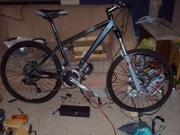
100_3740_bike_with_cyclone.jpg
Those tires won't be staying...
I have run the cyclone up on one of my 8s2p Turnigy packs and its running quite smooth. It seems quieter than my elation V2 ever was (same motor/gearbox type though). The chains seem to be aligned well.
One nice thing is the cyclone throttle is quite linear and runs at low speed compared to my cheapy throttle on the ecrazyman controller on my other bike( probably combined controller and throttle effects). The throttle on the cyclone is good in that although it looks the same as the one on the elation v2 kit it doesn't have the stupid stepped ramping up of speed the elation one had.
I'm going to use a magura anyway so apart from initial test the cyclone throttle will go in the parts bin until I find someone who needs one.

I got the heatsinks with my cyclone and they give a big hose clamp to hold them i guess but I want to glue them on so need to find some good cheap thermal epoxy I guess.

I'm planning to swap the gear cables to a black ones for aesthetic reasons only. I have removed the V brake from the back as I'm relatively confident of fitting the chain drive and disk brake on the same side at the same time when I get there.
The bike is now running Avid elixer R 203mm front and rear.

So far I think the 3 chain wheel cyclone is better than the elation V2 that has 3 chainwheels plus one for the motor.
The loss of one gear which you don't need anyway on the cyclone means that the cranks don't need to be weakened by stupid bends so should be less flexie as well.
Looking at things I may even be able to go for a slightly shorter BB than the asymmetric one supplied in the cyclone kit. It has about 20mm more clearance of the motor than necessary.

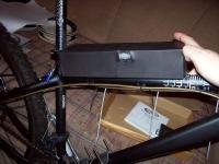
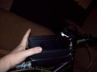
The photos below show that I should have plenty of room for different battery combinations. There is still room below the one below the top bar for a 4s 10Ah brick so alll up If should be possible go put equivalent of 3 * 8S 10Ah and a 4s 10Ah or that number cells in different configurations comfortable. The suspension and wheel will clear the one below the frame if it becomes necessary to have a pack there although I would prefer not to hang a battery in such a vulnerable position.
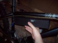
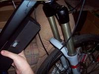
batt1_small.jpgbatt2_small.jpgbatt3_small.jpgcontroller_small.jpgView attachment 4

I'm just waiting from some LED indicators and control switches to arrive and then I'll lock down everything on the handle bars.
 
Back
Top