Rickys Keewee stealth RC bike buildlog

Small update
Not much progress on the mechanical.
Some progress with software but I've had the parents in town for a few weeks and hence was short off time.
The power electronics board is just about ready to be ordered. I just want to add a few spaces on the bottom for SMD caps across the DC bus near each switching device in case they are needed to assist the leaded ones. There is not a lot or room on the board for bulk electros and the board is big enough already! If all else fails I can add extra capacitance at the battery input on a little daughter board but since there is local caps for each switching device pair it shouldn't be necessary.

I found a convenient way to mock-up where the kart sprocket will sit before I organise a proper adaptor to hold it.
I discovered that some of the kart sprocket mounting holes lined up with the holes in an old 160mm disk brake I had lying around.
Another convenient fact is that the 81T sprocket I intend to start with is approximately 205mm diameter so it also doubles for checking possible clearance issues if I try and put a 205mm disc in as well.

So far it looks like if I move the kart sprocket inboard 10mm from the face of the disc mount on the Hub and I move the brake disc outboard by about the same I may just be able to squeeze them both in. I need to do some more detailed measurements.
I need to find a thin Hydraulic brake calliper. My Avid elixer R on the front needs about 20mm ( at widest part (where hose enters) from the centre of the disk to a possible sprocket which seems to be just a little too wide, not sure what their rear calliper is like.
Does anyone know of a narrow rear calliper?

I currently have a V brake on the back as most braking will come from regen but I would prefer to use a disk as it means I can mount the motor lower.

One convenient fact of this frame is that the rear drop-outs can be moved back about 10mm as under the alloy adaptor blocks that it came with there are 2 horizontal drop outs that go straight back. This frame is designed to work with the wheel back 10mm just using a couple of allen screws to hold it back. I think I would beef it up a little bit but the extra clearance from the seat stay would be useful for an outboard mounted disk brake.
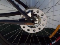
Kart-sprocket-mockup-small.jpeg
 
Ricky_nz said:
Does anyone know of a narrow rear calliper?
The Alhonga mechanical caliper apparently requires less than 14mm clearance.
ebikes.ca is selling these for use with the 9C rear disk hubs (currently no stock)
http://www.ebikes.ca/index.shtml
also seem to be available at Custom Motored Bicycles (not familiar with this supplier)
http://www.custommotoredbicycles.com/wheels_heavy_duty26inch_bicycle_brakes

The Tektro Novela calipers I have require >17.5mm clearance.(I am using with 19.6mm clearance)

Very impressive project! Kudos for the Kiwi :D
 
Thanks rebelpilot,
Good to get some numbers that arn't normally listed anywhere else online :)
You have got me thinking. Originally I was just thinking two psiton hydraulic but these are quite wide but if I was previously happy with the concept of a v brake with regen the mechanical disks open up possibilities. Come to think about it I may have some old tektro single sided mechanical disc callipers in the shed somewhere. I replaced them with hydraulic ones on one of my bikes and I don't think I got round to selling / disposing of them so if they are anything like the Tektro you mention I may be in luck. From memory they looked very similar the the ones you mentioned in construction.
I'll have to have a look through my boxes of leftovers in the shed on the weekend and hopefully find them.
It will be tight based on the numbers you gave but definitely preferable if at all possible to have some form of disc brake so I'll have to take some detailed measurements.

More parts here...
The other day when I was ordering parts for my 300W bike I ordered a few NTC's (Negative temperature co-efficient resistors) to fit into both its motor and into my Tturnigy 80-100 180Kv to allow temperature measurement and for use as an input to a thermal model of the motor that I will build into my controller.
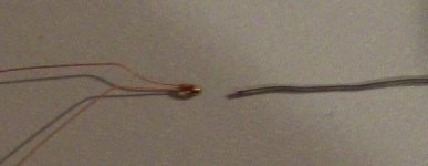
I ordered a few small glass bead 2Kohm NTC's figuring the response would be way faster than the motor. I also wanted small to avoid impeding airflow in the big motor. I looked at the datasheet and thought yep thats small enough buts its not until you get them in you hands that you realise how small they really are :D.
NTC-vs-20A-fusewire_100_2778-small2.jpeg
Higher res photo
NTC-vs-20A-fusewire_100_2778-small.jpeg
The above image shows the NTC and its 2 leads on the left and a piece of 20A fuse wire on the right.
The wires are uninsulated so I will have to solder some wires onto them and insulate somehow. I am certain that my solder connection will be bigger than the NTC. For insulation rather than have a big sleeve each wire I am thinking of a wipe of epoxy to keep the 2 wires apart and insulated. I will extend the leads with some insulated winding wire to bring them out of the motor.

I then need to find a suitable glue to attach the glass bead to the motor windings.
It would need to be thermally conductive tro some extent and not damaging to the motor windings.
Easy to remove to aid rewinding may be a bonus.

I hooked one up to my multimeter and this thing is sensitive and very responsive.
It responds fast enough to show a difference quickly after you start blowing over it the delay seemed to be more from the meters refresh rate.
 
Frame specs
Just found the specs/info for the frame here as it might be useful later in the build and I don't want to lose them.
This is basically just a cut and paste from the advertising on torpedo7.co.nz but since they no longer stock it who knows how long it will last there.
I have the 15.5" (395mm) size frame so I have edited out the 13" frame info
KEEWEE Stealth ’08 - Frame Only - NZ’s own trail legend is back and blasting for ’08! The Keewee Stealth was first unleashed 5 years ago and has proven to be one of the most diehard jump frames available. Made from solid 4130 Cromoly tubing unlike your little bro’s department store ride. The new breed of Stealth retains everything you loved about the old models but with a few tasty tweaks to really push the limits, the only question is how far will you take it?

Suitable for use with 24" or 26" wheels and now featuring adjustable chain-stay length, allowing you to alter the length from 420mm to 430mm. The International Standard disc brake mount system is attached to the adjustable drop-out to ensure perfect brake alignment regardless of chain-stay length. To top it off neat cable guides are welded beneath the low slung top tube so you wont hook you legs when throwin’ down tailwhips or double can’s.

Designed by Keewee, tested by Kiwis, made famous by you! Take your game to the next level.

The inside word :
While Keewee originally designed the Stealth for big air and downhill speed it has proven to be a Jack-of-all-trades, and is just as at home with a triple ring setup climbing mountains as it is hucking vert at the skatepark - ride it your way.

The Stealth has been designed to take a 100 to 150mm single crown fork, and bolt on gyro tabs alow you to dial in your setup and throw the bars at will.

Riding suitability guide:
Recreational X X X X
Cross Country X X
Enduro/All Mountain X X
Jump/BSX X X X X X
Freeride/Downhill X X X X X

Geometry 15.5 inch
A Frame Size 395 mm
Top Tube Length (Actual C-C) 533.4 mm
C Head Tube Length 115 mm
D Chain-Stay length 420-430 mm
E Head Tube Angle 69 deg
F Seat Tube Angle 72 deg
G Seat Post Diameter 27.2 mm
H Wheelbase 1050 mm
Seat Tube Diameter (OD) 28.6 mm
Weight: 2.9kg
Bottom Bracket Shell Width 68 mm
Rear axle spacing: 135 x 10mm
Headset type 1-1/8" External type
DUAL.png

Please note:
Due to the adjustable dropout/chainstay design it is recommended that a bolt through rear axle is used as some quick release skewers may not be long enough to securely tighten the rear wheel.
It is not recommended to move the rearwheel further back in the frame than the suggested 430mm.
V-Brake posts are included and are suitable for use with either 24 or 26" wheel sizes.

The low weight explains why it feels as light or lighter than my aluminium specialised hard rock but has a completely different look instead of huge formed ali it is nice small cro-mo tubes. I think will leave the frame black.
 
Caught the "supervisor" doing some quality control inspection.
supervisor_100_2784-small-comment.JPG

Now I've got a few other small non ebike projects out the way I should be able to find more time to work on this one again :)
I need to get a move on, I want to order the output stage PCB sometime during the week.
I need to stop procrastinating and order the damn thing :!: I guess its just the possibility of stuffing up in some way that makes the PCB useless.
Luckily the minor screw-up on the control board was easily worked around and has no impact on functionality.
I've had this board fully routed and basically ready to go for at least a month but it now needs final checking.

One small issue is the high voltage clearance around the LM5116 buck converter.
I can't get the clearance I would really like but its package limited so I guess as wide as possible is ok.
I'll probably conformally coat the board anyway when complete and tested to help give some protection on the bike.
 
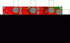
Sneek peek of my Power/IO PCB layout. The power devices mount below the board


power-hw2.GIF


This is a 4 Layer PCB
The power devices are TO-247 and are all mounted below the board and are bolted through the board onto the heat-sink.
Battery on right, phases at top.
DC CTs in phase A and B
buck converter for +15V for gate drive and some accessories.

Motor and controls connectors on left
The digital board from earlier in this build log fits into the connector on the bottom.
Still missing a few capacitor footprints.
Important traces will be build up by soldering braid where necessary.
 
Nice layout! :)

12x TO-247's is going to make it a monster. :)

They share the leg spacing, but did you by chance give them the 20mm tab spacing (rather than just 16mm of the TO-247) to enable both TO-264 and TO-247 options?
 
liveforphysics said:
They share the leg spacing, but did you by chance give them the 20mm tab spacing (rather than just 16mm of the TO-247) to enable both TO-264 and TO-247 options?

No unfortunately. I didn't realise about the TO 264 sharing the pin spacing. I packed the TO-247's in pretty tight trying to keep the board as small as possible, its 90mm x 150mm so not too bad but probably wouldn't want to make it much longer.

I don't think it would be possible to squeeze the extra 24mm into the design and keep the same length but then again
I haven't researched MOSFETS bigger than TO-247 So not sure how much gain there would be and stretching to board to around 175mm may not be a big issue if there is a big enough benefit.

Just looked at a ruler again to remind myself how big the board physically is (Too much looking at it in magnification on the PC) and 150mm ain't that much.


To put things in perspective:
Note outside dimensions of GM Magic controller case compared to my PCB.
My board is 15mm wider than the Golden motors magic controller (6 TO-220) and 40mm longer.
I'm estimating built up it out be about 40mm thick (set by bulk cap height) with the controller and bulk capacitors fitted but no heat-sink which is not much different than the thickest part of the GM controller.
The heat-sink may add 15mm - 40mm depending on application or fan cooling etc. There is an NTC input and a fan output in my system so temperature controlled fans is an option.

I don't know what case I will use. Maybe lexan bent and attached to a heat-sink so its all visible or hide it in a fiberglass 'tank' of some sort.
Don't want to add too much to the overall size just to accommodate a standard box.

Edit:
I currently have a set of IRFP4468PBF (100V) MOSFETS to build this up with when I get the board.
I'm not sure if I will actually need the 100V capability for the 80-100, yea right of course I do at some point :twisted: .
I have been considering ordering a set of
IRFP4368PBF the 75V version with 0.75mR lower maximum on resistance.
I don't have enough LiPo yet. I am waiting to order a pack once I get everything running on the 14S 2P (10Ah) pack I have currently before ramping things up.


I have just added an 1812 SMD footprint for MLCC caps across each pair of MOSFETS. This footprints its directly between the pads of the top MOSFET's Drain and the bottom MOSFETs source so extremely low inductance path.
I have managed to make room for another 11 of these capacitors across the bus with some at each end of the board.


This cap is assisted by a leaded MKP caps (EPCOS B32621 or similar) and then bulk electros.

I'm thinking of using AVX18121C105KAT1A for the SMD caps.

The 4 electros on the board will likely be Panasonic EEU-FC2A681 or similar. Due to board space requirements I need 7.5mm pin spacing on the bulk capacitors.

I few months back I replaced my old chinese soldering station with no choice of tips with a real one:
hakko_fx951.jpg
and brought a reasonable selection of tips for PCB work. I think looking at my power PCB where I have specifically turned off thermal relief in the high power section I will need to buy a bigger tip!
This is a 70W iron so no real problem there and it heats fast but I think a tip with a bit more thermal mass might be good. I haven't found their biggest tip locally but it looks like the 4mm one is available which is probably better than the 2mm one I have now.
This is a great iron (a bit expensive) but really nice and light with a thin barrel. The element is actually part of the tip which unfortunately makes the tips a little bit dearer than others but the heater is set in ceramic right inside the tip so it heats up fast.
 
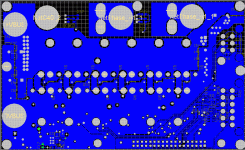
PCB Bottom Layer:
power-hw-bottom.GIF

Showing the SMD caps across the DC bus
 
Marvelously mezmarizing R-NZy

Micro device looks ace,

The ADC at 200ksps could be good with a pair of sample and hold circuits on the two phase current measurements.
Do you need to go to 500k sps for each Current signal or would 100k sps do?
More the merrier, if the AD7862 doesn't blow the budget.
Did you consider an AD with SPI on the Power board near the Current Sensors.
What's your target electrical RPM?
You had mentioned "Turnigy 80-100 to over 8500RPM mechanical (1000Hz) "

Will you have other AD inputs on a connector pins
eg Throttle, Brake,
1 wire - Multi button sensor for Cruise Control (1k-Econ/2k-Set/4k-Resume/8k-Acc/16k-Decel)

Will your electros be on the Top or bottom with the Fets?
Just wondering about the Stabilty of the Bus for the Left hand side Fets.
You could also allow several small LOW esr cans over the Fets so its distributed.
(Just noticed you new posts on extra Bus Caps)
If the holes are their you can choose to fit them or not. More the merrier.

You might want to leave space with Solder Resist gaps for track thickening.
Be carefull with High currents through middle layer copper.
Vias can help with heat build up and stopping track burnout.

Have you found a Heasink bar thickness that''s standard. Say 10mm x 30mm Bar.
Or as others have suggested, using mini link bars for the twin FETS on the low side that are at U,V &W potential (oh you've got A,B & C)
This way you don't need insulated pads behind the TO247AC (if used) you put them behind the three minibars (... I'm thirsty :lol: )
Will the heatsink need to be fastened to the PCB?
There doesn't appear to be any holes for this?

Also the Heastink can be a current path the Tab and center Drain Pins.
But be careful it doesn't make the Drain Leg a main current path to a Capacitor.
Some times happens if battery positive is linked to heatsink.

As you know too many ways to blow you self up (sick of ...skin the cat analogy)
So please ignore my comments if they bug you. (Splat....*...)
... Don;t ant to drive you crazy with my rants''
It's look ace.

Be one with the electron and the EM force will lead you :eek:
 
7circle said:
Marvelously mezmarizing R-NZy
The ADC at 200ksps could be good with a pair of sample and hold circuits on the two phase current measurements.
Do you need to go to 500k sps for each Current signal or would 100k sps do?
More the merrier, if the AD7862 doesn't blow the budget.

Did you consider an AD with SPI on the Power board near the Current Sensors.
Just went overboard on ADC, better to have too much rather than not enough. I really wanted the simultaneous sampling feature.
I didn't find an SPI adc with simultaneous sampling that I liked and using one on a parallel bus makes it possible for me to determine exactly when the currents are sampled.
I want to play around with sensor-less vector control so extra performance and control is always a good thing.
The SPI idea would be good for keeping noise from the switching board out of the critical current inputs though by localising the analog signal path.

I figured cost wise the ADC is cheep compared to the MOSFETS and since I would rather the controller be done right than done to a price point. for say a smaller 6-FET controller the micros on chip ADC's could be used but they are quite slow when you have to use a mux on them to get the 2 currents.

7circle said:
Marvelously mezmarizing R-NZy
What's your target electrical RPM?
You had mentioned "Turnigy 80-100 to over 8500RPM mechanical (1000Hz) "
Yes I'm targeting 1000Hz operation for sinewave sensorless vector control but I will also probably do a simple sensored trapesium control mode that allows much faster operation.
I will of course try and go faster but I expect losses in the motor to rise at some point. The 1000Hz means I need to have my software current controller running at a significantly higher rate to get any resemblance of a sinewave and it is this that will limit it in sinewave mode.

Since the electrical RPM supported its is entirely dependent on the processor performance and since I'm estimating this until I have some more control code written its all a bit of a guess. I say 1000Hz electrical as I am confident based on whet I have seen so far with this processor and comparisons to a TI DSP I use at work. It should be able to do better than this.

edit: 1000Hz electrical -> 1000 electrical rev per second -> 60000 RPM electrical.

I have got most the software infrastructure in place to allow easily switching between modes of operation.

7circle said:
Marvelously mezmarizing R-NZy
Will you have other AD inputs on a connector pins
eg Throttle, Brake,
1 wire - Multi button sensor for Cruise Control (1k-Econ/2k-Set/4k-Resume/8k-Acc/16k-Decel)
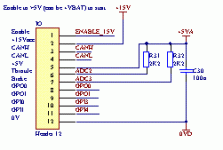
I have exposed 2 ADC inputs on the control connector for throttle and ebrake along with a few digital IO lines so it would be a matter of programming to use them for any desired purpose.
For my bike I'm planning to do a separate dash controller and to connect it to the motor controller over a CAN bus interface but having the option to use a simple resistive setup could be handy for testing or for less complex setups.

7circle said:
Marvelously mezmarizing R-NZy
Will your electros be on the Top or bottom with the Fets?
Just wondering about the Stabilty of the Bus for the Left hand side Fets.
You could also allow several small LOW esr cans over the Fets so its distributed.
(Just noticed you new posts on extra Bus Caps)
If the holes are their you can choose to fit them or not. More the merrier.
I am concerned about keeping the +vbus and 0vbus well decoupled. I thought about caps above the + side FETS but they may interfere with where I need to build up the traces with braid for the phase outputs.
The electros and leaded MKP caps will be mounted on the top side but the SMD MLCC will be on the bottom side with virtually no track length. I'm hoping the SMD caps are enough to hold things together.

7circle said:
Marvelously mezmarizing R-NZy
You might want to leave space with Solder Resist gaps for track thickening.
Yes that is planned, I've been leaving that till last but I will expose areas of the phases and the + and - bus polygons once I have no other changes to the board.

7circle said:
Marvelously mezmarizing R-NZy
Be carefull with High currents through middle layer copper.
Vias can help with heat build up and stopping track burnout.
This is something I'm a bit concerned about. currently the only currents in the inner layers are because of paralleling with the external +bus and -bus polygons but getting the heat out is a problem as you say. I may add a few more vias to help get the heat out. Hopefully using thick copper on the outer layers and beefing them up with braid will prevent issues by providing a lower impedance path than the internal fills or at least altering the current split so most flows on the outside.

7circle said:
Marvelously mezmarizing R-NZy
Have you found a Heasink bar thickness that''s standard. Say 10mm x 30mm Bar.
Or as others have suggested, using mini link bars for the twin FETS on the low side that are at U,V &W potential (oh you've got A,B & C)
This way you don't need insulated pads behind the TO247AC (if used) you put them behind the three minibars (... I'm thirsty :lol: )
Will the heatsink need to be fastened to the PCB?
There doesn't appear to be any holes for this?

Also the Heastink can be a current path the Tab and center Drain Pins.
But be careful it doesn't make the Drain Leg a main current path to a Capacitor.
Some times happens if battery positive is linked to heatsink.
I haven't looked for a standard heatsink bar but I have fund a heatsink that comes in a 100mmx150mmx30mm which would work nicely behind the board.
I decided to avoid the complication of having a bar run along the +ve fets and then having to insulate the bar from the heatsink.
There is a set of pads for standoffs around the edge of the board (3 per side) with a few in the middle that may not have shown up too well in the images I posted that will be used to support the PCB.

7circle said:
Marvelously mezmarizing R-NZy
As you know too many ways to blow you self up (sick of ...skin the cat analogy)
So please ignore my comments if they bug you. (Splat....*...)
... Don;t ant to drive you crazy with my rants''
It's look ace.
My cats not too fond of the skin a cat analogy either :lol:
No problem its good to see others views especially since they can sometimes prevent expensive mistakes. Sometimes the mere fact of answering someones question can highlight an issue (happens all the time between me and other software engineers at work).
Since this is by far the highest power electronics I have designed myself there is definitely a chance of design problems.

Hopefully I havent missed anything. If I have or if you have other questions or suggestions fire away :)

Ricky
 
Power / IO board IO connector pinouts

Control Connector:
control-connector.GIF


Motor connector:
motor.GIF

The 3 hall inputs can also be used for a rotary encoder if the software is written to use the CPU's hardware support for that.
 
I can understand that the ADC having diff+/- and simultaneous sampling will help deal with the head ache of aligning phase measurements.
Building your own analogue FET switches to make your own Sample and hold front end is tough too.

Using remote ADC with SPI and relying on Serial commands to start sampling would be annoying, but using a digital trigger signal to start CONV is not that uncommon.

The Cortex 12bit 200k 8 channel has a lot of features, like DMA. I'm sure once you stablize the control loop withthe external ADC you'll then be able to decide if the internal ADC has sufficient capacity.
Looks like you don't have to shut down the Core to get accurate measurements like some older uCro's needed to do, causing massive delays in control loops.
And is another good reson for you choice of external ADC.

So I wonder what type of Current sensors your using.
Do you need to buffer these signals?
Do they justify 12 bit 500k S/s.
Its a long trace run pack to the AD though all that war zone of 75V to 100V PWM and 100A currents with ripple.
Then through a connector or ribbon lead with no adjacent analogue ground wires. Hopefully is a soldered dual row header to the top Brain Board.
So differential input will be limited.
file.php


If you like even bets you could put a third AD on the power board.
What's wrong with the AD7861 its the same as the ADS7862 but with a serial interface.
Or even better the ADS7863 is pin compatible with ADS7861 (oops was 7862) with more features.
It can operate with just 4 control signals or more for extra speed etc.
It has variable Ref D-A output, very good for gain control.

1000Hz sample with 32 samples per cycle would be 32000 sps

So with (Edit .... I'll leave the DSP calcs to you, my brain's not up for it yet.)

Its a challenge, but it looks like your up for it.

7¢ :wink: (Edit I'm learn'n too much slow down ... )
 
7circle said:
I can understand that the ADC having diff+/- and simultaneous sampling will help deal with the head ache of aligning phase measurements.
Building your own analogue FET switches to make your own Sample and hold front end is tough too.

Using remote ADC with SPI and relying on Serial commands to start sampling would be annoying, but using a digital trigger signal to start CONV is not that uncommon.
True, using the parallel one Is quite nice in that I can read it quicker
7circle said:
The Cortex 12bit 200k 8 channel has a lot of features, like DMA. I'm sure once you stablize the control loop withthe external ADC you'll then be able to decide if the internal ADC has sufficient capacity.
Looks like you don't have to shut down the Core to get accurate measurements like some older uCro's needed to do, causing massive delays in control loops.
And is another good reson for you choice of external ADC.
Yes. I put the overkill ADC on the control board also because I have some other projects I plan to use it for but for the motor controller It may be possible for cost reduced versions to use the cortex on chip ADC.
Currently on my power board I have most ADC inputs assigned. I may have one of the cortex ones free. If so I will take you sueestion to put it on the control connecter.
I can't check now. The schematic and pcb are in windows and I'm currently in Linux. I will check later tonight when I go back into windows to tweek the layout.

7circle said:
So I wonder what type of Current sensors your using.
Do you need to buffer these signals?
Do they justify 12 bit 500k S/s.
Its a long trace run pack to the AD though all that war zone of 75V to 100V PWM and 100A currents with ripple.
Then through a connector or ribbon lead with no adjacent analogue ground wires. Hopefully is a soldered dual row header to the top Brain Board.
So differential input will be limited.
ACS758. If they don't work I can use some external ones. They have 120 kHz typical bandwidth.
http://www.allegromicro.com/en/Products/Part_Numbers/0758/
Any extra ADC performance can be used for oversampling to reduce any noise issues etc.
I have just put a +/- 200A one of these in a box with a couple of brass bolts and a 5V regulator so I can use it as a current shunt for my meter and scope :D much cheaper than commercial solutions and it works for both AD and DC.
These are single ended output centered on 1/2 VCC.
The trace runs past the control connector on the side of the board and has a ground plane that is separate from the high power section. This long trace issue does concern me a little but I have organised things so a couple of cuts with a knife and I can run screened lines from the CT's directly back to the digital board. I coulden't put the CTs at the bottom of the board as the pase leads would have interfeared with the digital board.

The digital board will sit 15mm above the power board on stand-offs so no long cables. I probably could have put a few more grounds around that area but the digital board is made so I'm kind of stuck with it for now. If there is issues there are enough grounds that I could rig up some kind of shield.
All ADC lines have a very small filter on the digital board before the ADC which should kill noise spikes without slowing things down. Also I should be able to control the ADC so that it samples at a relatively low noise point which combined with oversampling if necessary should help a lot.

7circle said:
If you like even bets you could put a third AD on the power board.
What's wrong with the AD7861 its the same as the ADS7862 but with a serial interface.
Or even better the ADS7863 is pin compatible with ADS7861 (oops was 7862) with more features.
It can operate with just 4 control signals or more for extra speed etc.
It has variable Ref D-A output, very good for gain control.
I probably wont for this power board.
I do have an SPI connector on my control board but it doesn't come out the main PCB connector so If I want to do a different power board I have SPI available. Originally when I did the digital board design I had decided for ultimate speed parallel was the way to go and since that board is working I'll leave it how it is for a while. I need to have the CT lines come to the digital board anyway for the high speed hardware current trip for when the software loses control.
Another issue is the speed of the SPI interface is limited on the LPC (just like TI TMS320F28335 etc). At the rates I'm looking for SPI could become an issue. The IO pins on the LPC top out at 20MHz (check?). I also wanted to simplify some of the software for controlling when things are sampled. this is probably no real reason that I couldn't be used, just not in the scope of what I was looking for at the time.
I can have the values in the micro is <1us after sampling on the parallel one and to match that would require 24MHz or more on the SPI bus.
I'm not sure I would want 24MHz running accross the power board to the CT area either.
The other thing is I may have had other limitations that I have forgotten as my original design for the control board was for the LPC2368 and I changed at a late stage after most of the board was layed out and moved some things around. ( the oh shiny, must have that problem. I decided that was the final change to the DSP board and left it at that). Actually 120MHz vs 72 MHZ when I want very high control rate didn't leave me much choice.

7circle said:
1000Hz sample with 32 samples per cycle would be 32000 sps
Yep I'm thing the ADC will be read at at least 8KHz probably running even faster. The PWM rate will probably be 12KHz or faster and if possible I may run the ADC at that rate! the faster things run the better the current control of the motor will be.

I'll be tapping the knowledge of some of the gurus at work that have designed motor drives for a previous company :D.
I have a reasonable understanding but some of the finer details I will have to lean on them.
My day job involves writing code to drive 150KVA 3 phase inverter modules that are paralleled up to the several megawatt level.

From what I know I should have enough time on this processor at 120MHz to run critical control code at at least the 8KHz rate.


EDIT:
One other point I think I missed is that by keeping all the digital and high speed stuff on one board I have protection networks on all lines that leave the digital board. All input lines can tolerate 100V connection as they are protected with a clamping/limiting network (not all at once but on a single line).
Outputs because of impedance issues cannot have quite as much series R so a lower but still significant voltage could be connected and result in no damage to the digital board or just damage to the protection parts. These assume no impedance external to the digital board is involved.
Its a balancing act as series impedance must be kept low but to limit damage if the inevitable happens is a good thing.

EDIT:
From some of the app notes about these sensors a piece of copper can be used in parallel with the internal slug if more then +/-200A is required. No special shunt wire is required as the internal slug is measured in uR due to using a hall sensor. They even give one example if a sensor attached to a copper bus bar with a notch in to reduce its width next to the sensor. Of course increasing the maximum current reduces the sensitivity meaning less accurate current readings from the ADC.
I will probably save this modification for when I want to make a turnigy 80-100 glow like a lamp :twisted:
 
More parts:
A few large lugs and a heatsink arrived today :)

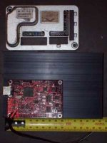
The size of the heat-sink shows the whole size for my controller PCB.
The heatsink is 100mm x 150mm and my pcb is 92mmx145mm.

here is a few photos for comparison

Control PCB sitting in correct location relative to heat-sink. in reality it will be 15mm above the power board that will be 10mm above the heat-sink
There will be 4 40mm high electros mounted on the power board so they will set the total thickness of the controller at 90mm thich including this heat-sink. This heat-sink may be overkill on the bike but rather than start small I figured a bigger one for bench testing where there is no wind and then reduce the fin length for the final install on the bike if it dosen't cause any heat issues.
ctrl-heatsink-100_2792.JPG

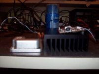
Some comparisons with the back cover of a Golden motor magic 50A controller (really 30A continuous,l 50A peak as I understand it) uses 6x TO-220 MOSFETS.
Note that my controller used 12xTO-247. Lots of power in a small space! I like a challenge!
size-1-100_2794.JPG
size-2-100_2795.JPG
 
I didn't have a complete list in one place so here it is for quick reference with a few more comments than the annotated connector pinout.
Current ADC assignments on my power board

[pre]ADC channel Description
0 +15V monitor
1 unassigned <- Has a HW trip comparator. maybe tie to +V Bus monitor
2 Throttle
3 Brake
4 Heatsink Temp
5 Motor Temp
6 Phase A I <- HW trip
7 Phase B I <- HW trip
8 +V Bus monitor (Dosn't really need to be this fast but speed allows better
protection under fault conditions).
9 unassigned <- could bring out to one of the input pins on the control
connector but I suspect there isn't room for another trace.
There is a tight spot in the layout in the way[/pre]
 
Excellent thread Ricky, top notch!

You may have stumbled on it already, but I think you may find this blog interesting:
http://scolton.blogspot.com/search/label/3ph

He is doing the most thorough work on BLDC and BLAC motor design/controller design that I have seen (granted, i don't have an IEEE membership).

Anyways, keep up the good work, hope you find the link usefull.

-Matt

PS:Don't know if you know of them, but ST's STM32 line of ARM (cortex M3) micros is also quite interesting.. and cheap too. Also, you can get a dev board for nearly nothing:
http://www.st.com/internet/com/TECHNICAL_RESOURCES/TECHNICAL_LITERATURE/DATA_BRIEF/CD00277245.pdf
 
matt_in_mtl said:
You may have stumbled on it already, but I think you may find this blog interesting:
http://scolton.blogspot.com/search/label/3ph
He is doing the most thorough work on BLDC and BLAC motor design/controller design that I have seen (granted, i don't have an IEEE membership).
Interesting link, I'll have to find some time to read through it. Its always good to see what others are doing with the technology.

When I was looking around I ended up using the LPC1769 cortex m3 but there is definitely a lot of other processes like the ST around with useful hardware integrated to aid motor controllers. Years ago I would have probably just used a TI DSP but since GCC is pretty good for ARM and TI charge for their DSP development tools something cortex m3 based was an easy choice.
The chips are relatively cheep and with good free dev tools and cheep jtag debuggers available the cortex m3 based chips are great.
 
This is a great write up Ricky!! I am lost in the tech language, but am reading through it anyway in the hopes that something will stick. Thank you for posting this up.

I was just wondering if you could give a short synopsis on what has been accomplished thus far in layman's terms. It looks like you are near completion on the board that monitors and controls the gate drivers and FETs, is this correct?

I'm sure you will have a market for this monster if you decide to sell kits or something, hopefully this will fill a niche and give some the opportunity to see 20 hp on an ebike! 8)

Also, if you want I have what is called a "top hat" adapter that shifts the sprocket inward toward the spokes giving room for your disc brake as well on the same hub flange. Here is a pic:

photo-135.jpg


photo-134.jpg


You could then use washers along with a smaller disc to get the necesary clearance if this is not enough room.
 
Hi etard
etard said:
This is a great write up Ricky!! I am lost in the tech language, but am reading through it anyway in the hopes that something will stick. Thank you for posting this up.
I was just wondering if you could give a short synopsis on what has been accomplished thus far in layman's terms. It looks like you are near completion on the board that monitors and controls the gate drivers and FETs, is this correct?
I'm sure you will have a market for this monster if you decide to sell kits or something, hopefully this will fill a niche and give some the opportunity to see 20 hp on an ebike! 8)
I probably need to create a glossary of some of the terms.
Ok current progress simplified, there are two circuit boards.

Control board (the brains)
Build and tested with a basic operating system that can read voltages from its inputs and access a micro SD card. Basically enough to know the hardware is working. I need to find time to write the software soon.
This board has a 120MHz LPC1769 microprocessor to do all the number crunching.
It also contains a decent ADC (analog to digital converter) to allow accurate and fast measurement of signals from the Power board below.
Need to spend some time getting the USB software working but the hardware is correct.

Power Board (The brawn)
This board contains:
a) gate drive circuit to turn the 12 MOSFETS on and off reliably.
b) IO connectors and interfacing. mainly converts input voltages into suitable ranges for the control board.
c) current measurement in two of the phase wires using a DCCT = Direct Current Current Transformer. A hang over from ACCT. an AC CT really is a transformer whereas a DCCT is actually a hall effect device measuring the current in a wire magnetically and electrically isolated. By measuring the current in two phases I know the current in all three.
d) NTC - Negative temperature Coefficient resistor used to measure heat-sink temperature and an input for one attached to the motor windings.
e) 5A 15V power supply. This is used to run the gate drive circuit and to feed the on board power supply on the control board. There is an output of this 15V on the control connector so I can be used to run lights etc. The control board monitors the 15V to ensure that it is always high enough to allow switching the MOSFETS.

I have finished the circuit diagram for this board and have the circuit board designed on the PC.
I just need to make a couple of minor fixes and then give it a final very detailed check before ordering.
I'm doing that right now so maybe I'll order on Monday :D, Once I order it it will be at least 12 days until I have the bare boards in my hands.
Maybe I can be building up power boards and debugging over the Christmas break :twisted:
I will take powering up the board quite slowly to avoid costly mistakes!
I will test the individual parts listed above in isolation where possible.

I will probably build up a small batch if there is interest once I get the software running unless someone is keen sooner.
I really would like to recover some of the board setup costs for this hobby project :lol:
Once I have the current control and power board combination working it would be easy to make a different power board and run the same control board/software.

Have I missed anything?

etard said:
Also, if you want I have what is called a "top hat" adapter that shifts the sprocket inward toward the spokes giving room for your disc brake as well on the same hub flange. Here is a pic:
You could then use washers along with a smaller disc to get the necessary clearance if this is not enough room.
Sounds interesting. I could be interested in buying one if the dimensions make it easy :). Since I don't have a lathe that was the one part I was considering paying an engineer to make but if you already have one it would be good and would save on having a custom one made.

Is the outer part big enough diameter to bolt a kart sprocket onto? ie around 150mm diameter or would it need a plate to bring it out to that diameter.
Yout top hat part looks pretty solid as I imagine it needs to be to cope with loads of pulling from a chain offset to one side.
 
Making progress on PCB. I think I have done the last major changes and its looking pretty good :D .
Plenty of pinning layers together where necessary.
It passes DRC (Design Rule Check) apart from 4 pad clearances which are caused by the EP footprint under the synchronous buck converter which is a limitation of the package.
The gap is actually sufficient but I was using bigger clearances to avoid unnecessary limitations on voltage. The on board 100V -> 15V converter can be disconnected to allow higher voltages and by disconnecting this from the input voltage the clearance issues disappear. It would be possible to patch in some form of pre regulator but a small external switch mode converter would be preferred.

I need to do a final check of footprints etc but late at night isn't the time for that so that can happen tomorrow hopefully.

I just fed the board data into PCB cart
the setup costs for the board is 235 USD so I don't want any mistakes!

Not sure how to get the plate through slots for the CT into the gerber correctly for PCB cart.
I read somewhere that you can set altium to output drill slots or routes.
Oh well thats a problem for Monday.
 
I was just about to starting a final check of footprints etc and while looking at the board deciding where to start I realized that there was still room for more caps across the +VBUS and 0VBUS right next to the MOSFETS. Not big ones but 1206 but I figured that it was worth adding these as I can always leave them off when assembling the board if they prove unnecessary.
So the board just gained another 6 SMD capacitors right across the MOSFET pairs. These are within approximately the length of an 0805 caps pads from the center of the MOSFET +Vbus and 0vbus pads. The reason they are not closer is because of the other SMD cap that they are in parallel with :lol: .
I will more than likely put 10n or 100n caps in these new positions. There is solid fill connecting these caps to the +vbus and 0vbus so it should all be very low inductance.

So much for finishing checking the board today :lol:.
Oh well I can't see any more space for caps across the bus and haven't thought of anything else to add so let the checking begin!

I'm also down to one clearance error only :D and that's the one under the synchronous buck converter chip that I can't improve but it is adequate anyway.
 
Good choice on adding more cap. :) A board can never have too much cap. :)
 
liveforphysics said:
Good choice on adding more cap. :) A board can never have too much cap. :)
Very true and if there isn't enough then I can stack them being SMD :)
 
epic!!! nice job man!!! :mrgreen:
sorry for asking a stupid question, any idea on if and when your going to be selling these monsters? if so how much well u be selling them for? thanks
 
Back
Top