Solid vs Stranded wire

Eclectic

1 kW
Joined
Aug 6, 2012
Messages
308
Location
Southern California (San Gabriel Valley)
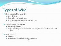
I understand the flexibility with finely stranded silicone insulated wire but if I don’t need flexibility would solid copper wire (with thermoplastic insulation) be a better (and less expensive) conductor? I’m nowhere near an EE so I don’t understand things like skin effect.

Specifically, I want to replace the phase wires from the controller to just outside of the hub. The wire coming out of the controller and the hub would still be the original stranded wire but I thought that since the part that I am replacing would be permanently attached to the frame I could use solid. I plan on using 4mm bullets and 12ga solid wire that I buy by the foot at my local home improvement store.
 
Thanks dnmun
 
I wouldn't use solid in a high vibration environment. I have never seen it done, but would fail such an installation (I'm a 2391 man) It's not an electrical issue, It is a mechanical one. The other temptation would be to shape it all snug to the frame, ignoring the minimum bending radius. Starting the failure off before it ever saw the road.
 
That's right, solid wire is OK for its electrical function, but no good mechanically. When you bend copper, it work-hardens. Then, with more bending, it cracks and breaks, which is why you don't find it very often in mechanical devices. The vibration from riding your bike is enough to make it break.
 
I agree. You don't see solid wire on cars do you? But you don't exactly require the very very fine strands of RC wire either. If automotive wire is cheaper, use that. But not house romex.
 
For frame runs between motor axle/controller I like heavy duty 12ga 3 conductor power tool wire sold by length at Home Depot. Designed for flexibility and the heavy duty sheathing can be tightly cinched to the frame with no damage to the conductors.
 
The fine stranded silicone wire is less likely to fatigue in high movement areas like around the steering head if you have a front wheel drive. I have also noticed it is less likely to fatigue at a solder joint so you can get away with RC connectors soldered directly to the plug without any stress relief. This technique was bad news before the RC cable became readily available. If you use the automotive cable with fewer strands you should stress relief the cable. Soldering can cause an area of low flexibility at the solder joint which can fail under vibration or constant flexing. Some form of mechanical support is recommended. It could be as simple as some heat shrink over the joint or cable tie to something solid so it does not flex at the joint.
 
By what i know about electricity, alternated current(and that's what goes thought phase wires) creates a skin effect, which turns the conduction in the center of the wire harder, if not impossible. But certainly less conductive than the skin. Stranded wire is better to avoid it since each strand is isolated from the others and also twisted. If the stranded wires does not attend to this specifications, there is no electrical difference between then...
 
mateusleo said:
By what i know about electricity, alternated current(and that's what goes thought phase wires) creates a skin effect, which turns the conduction in the center of the wire harder, if not impossible. But certainly less conductive than the skin. Stranded wire is better to avoid it since each strand is isolated from the others and also twisted. If the stranded wires does not attend to this specifications, there is no electrical difference between then...

While the PWM frequency of our controllers is high enough that large solid copper could make a difference, those pulses aren't AC. It's the motor commutation frequency, magnet number X rpm, that determines the alternating current frequency, but our motors (other than maybe some small extreme rpm
RC motors) don't get near the 10khz or so operating frequency where solid vs stranded can make a difference due to skin effect. With a typical 48 magnet hubmotor, that would be over 12,000 rpm, about 10X the max rpm we see. As a practical example, Thud has rewound a lot of 4-6krpm RC outrunners that have 12-16 magnets with solid core phase windings with no ill effects at all.
 
John in CR said:
mateusleo said:
By what i know about electricity, alternated current(and that's what goes thought phase wires) creates a skin effect, which turns the conduction in the center of the wire harder, if not impossible. But certainly less conductive than the skin. Stranded wire is better to avoid it since each strand is isolated from the others and also twisted. If the stranded wires does not attend to this specifications, there is no electrical difference between then...

While the PWM frequency of our controllers is high enough that large solid copper could make a difference, those pulses aren't AC. It's the motor commutation frequency, magnet number X rpm, that determines the alternating current frequency, but our motors (other than maybe some small extreme rpm
RC motors) don't get near the 10khz or so operating frequency where solid vs stranded can make a difference due to skin effect. With a typical 48 magnet hubmotor, that would be over 12,000 rpm, about 10X the max rpm we see. As a practical example, Thud has rewound a lot of 4-6krpm RC outrunners that have 12-16 magnets with solid core phase windings with no ill effects at all.
Indeed, the operating frequency is very low, didn't think about that...
 
My thinking is that the fatigue is more likely to happen from whatever maintenance you have to do, rather than just road vibration.

At some point, you get a flat, and then you start bending that wire around. Plugging and unplugging, etc. Might take some time to fatigue, but eventually it does stiffen up, then might start to crack at the plug.

In the end, you do have relatively cheap stranded options, such as 12g power tool wire, old extension cords, etc. You can double up 16g wires to carry larger currents. How about some nearly free old computer power cords?
 
dogman dan said:
My thinking is that the fatigue is more likely to happen from whatever maintenance you have to do, rather than just road vibration.

At some point, you get a flat, and then you start bending that wire around. Plugging and unplugging, etc. Might take some time to fatigue, but eventually it does stiffen up, then might start to crack at the plug.

In the end, you do have relatively cheap stranded options, such as 12g power tool wire, old extension cords, etc. You can double up 16g wires to carry larger currents. How about some nearly free old computer power cords?
Also, no one is likely to use more than 4—6 meters of wire, ends up cheap due to amount
 
Copper gives up quicker than people think. Years ago it was standard practice to strip the sheath of t&e by pulling the cpc with pliers. The non-insulated cpc(earth) would rip through the outer sheathing easily. This practice is now banned, as the bending radius of the cpc where it was ripping the sheath is too great and in just one bend of the copper it was damaged enough to fail during testing.

If the bend radius is exceeded, you can't just bend it back. It is ruined. Forget work hardening in terms of bending back and forth. It is weakened long before it snaps.
 
Are you considering using the kind of solid wire that is used in houses?

Yep, it is all about where the fatigue happens when the wire bends and vibrates.

If you can secure the solid wire in a why that it doesn't flex and rub much then you will be fine. But, think about where you will solder or connect the solid core with the stranded wire. Will the stranded wire cause the solid wire to vibrate enough to eventually break at the point where the solid wire is secured to your frame? One way to stop that is to secure the stranded side as well as the solid side on both ends of the solid wire "run". But by doing that you will have to make the stranded wire segments longer then you thought you might have to. You would need to extend the stranded wire an extra 6 - 12 inches to properly secure the stranded wire from vibration. At this point, the solid wire length has been reduced to the point that it no cheaper in price then stranded wire.

If you have all the wire and want to do it, why not? I IMO it is just as easy to get an old 3-wire extension cord, or computer cord, cut out two equal lengths that will work for you, wire them in parallel and use that. Any worries about vibration causing breakage in your wiring are eliminated.

:D
 
My new favorite is wire for the leads on welding machines...readily available locally, maximum flexibility and tough insulation. The smallest I could find near my house is 4ga, but I've seen 6ga. The first place I checked online was just over a buck a foot for 6ga, so it's reasonably priced. To me, wire is like dropouts and there's nothing at all wrong with a bit of overkill, but once I go 2wd I'll actually need at least 4ga anyway. My controllers may be trembling a bit staring down that copper pipe with 20ah of 65/130c Nanotechs at the other end, but the doubled up 10ga just wasn't cutting it anymore. :twisted:
 
I can't say about you guys, but where I live, Brazil, we have stranded wires for houses electrical installation, but they are not twisted and the insulation is not silicon, but they cost same as hard wires and are a lot more flexible
 
stranded wire is used in residential and commercial wiring applications where the cable has to be pulled through conduit so the stranded will flex enuff to allow the wire to slip through the conduit. solid romex is used where the wiring is done at rough in and the wires can be installed manually without pulling them through conduit.

i think the guy who started the thread intended to use the solid wire for the section of conductor that is fixed to the frame and was gonna use stranded on the ends where the wires have to flex. it should not be used where the conductor has to connect to a front motor and the wires to the motor will be flexing with every turn of the handlebars.

my first twistoff rebuild of a goldenmotor used 12AWG solid wire through the axle and out to the outside. it was nearly impossible to make the wires turn inside the motor where they come out of the hole through the axle. i would never do that again.
 
dnmun said:
.........
my first twistoff rebuild of a goldenmotor used 12AWG solid wire through the axle and out to the outside. it was nearly impossible to make the wires turn inside the motor where they come out of the hole through the axle. i would never do that again.

Solid wire through the axle is definitely a PITA....... :lol:
In this case I was able go get 11awg solid wire through the axle, but it was a real Push-pull-push-pull kind of a battle. Not easy at all!

11 awg pull 1.JPG

awg 11 pull 2.JPG

:D
 
Personally I try to use as little wire length as possible. The skin effect mentioned above is really only relevant at high frequencies such as radio frequencies. Short cables and as few connectors as possible reduce the losses in the system and make it more reliable.

The availability of good quality silicon RC cable at really very cheap cost from the likes of HK makes it pretty silly to use anything else. Use over rated gold plated connectors and keep cables short and you should have a reliable system.
 
Here in the UK the rules about solid conductors versus flex with mains power are quite specific.

Building wiring for our 240v ac uses "twin and earth" consisting of two insulated solid cores carrying the live and neutral in single phase, with a bare solid core earth between them, covered in an outer flat pvc sheath.

All mains electrical installations in Caravans and Boats require three core multi stranded flex instead, because of the potential vibration, as already mentioned on this thread.

Remembering the opening poster's exact question, the actual windings in the motor are solid core copper, but if they're being extended anywhere past a point where they may be flexed again at a later date, such as just outside the hub entry point, then they will eventually fracture.
 
Wow... Look what happens when you don't visit ES for a couple of days. I thought this thread was dead on Friday.

I'm a computer guy, not an electronics guy but IIRC we used solid wire on long network runs because it had less attenuation and signal loss (both good attributes). Since the only wire I would be replacing would be strictly on the seat stays, flexing and bending should not be a problem.
Eclectic said:
The wire coming out of the controller and the hub would still be the original stranded wire but I thought that since the part that I am replacing would be permanently attached to the frame I could use solid. I plan on using 4mm bullets and 12ga solid wire that I buy by the foot at my local home improvement store.
I plan on putting 4mm bullets on the end of the stranded wires coming out of the controller. I also anticipated leaving enough stranded phase wire coming out of the motor to reach the solid wire strapped to the seat stay (connected again with 4mm bullets). That way, it would be easy to remove the rear wheel.

So these are my thoughts:
Less attenuation and more current for a given gauge
Smaller physical size for both the conductor and insulation
Easier to route cleanly
Slightly less expensive

I hadn't thought about zip tying the stranded side of the connections down also so there would be less vibration on the connections but it seems like a good idea.

PS - I've been using solid 12ga and 16ga straight along the top tube (lighting sub-system) for ~2,500 miles now and so far no problems but that isn't anywhere near as mission critical as phase wires.
 
Computer networking uses frequencies in the megahertz or gigahertz region, where attenuation from skin effect might be significant. It's just not relevant to brushless hub motors.

There's also no practical difference in size/current capacity for stranded Vs. solid wire.
 
In physics we got to choose our lab experiment so I planned on pushing diffrent currents through 18 AWG and 22 AWG wires but hobbyking only sent me the 18 AWG wire....

My lab partner and I compared:

- Solid wire
- low stranded normal automotive wire
- Hobby King high stranded wire

The low stranded out performed the solid and high stranded wire. At over the rated current the high stranded performed extremely bad.

Attached is a powerpoint with lots of graphs that everyone is free to look at. Unfortunately it wont let me attach the powerpoint so I just converted it into a bunch of pictures.

John, I hope you don't mind I used your picture for the presentation, I did cite it.

I would love to do more testing at higher currents but I don't have the equipment to do it.

Slide1.JPG
 

Attachments

  • Slide14.JPG
    Slide14.JPG
    69.1 KB · Views: 1,750
  • Slide12.JPG
    Slide12.JPG
    64 KB · Views: 1,750
  • Slide11.JPG
    Slide11.JPG
    74.1 KB · Views: 1,750
  • Slide10.JPG
    Slide10.JPG
    71.6 KB · Views: 1,750
  • Slide8.JPG
    Slide8.JPG
    65.6 KB · Views: 1,749
  • Slide7.JPG
    Slide7.JPG
    89.7 KB · Views: 1,750
  • Slide6.JPG
    Slide6.JPG
    68.6 KB · Views: 1,749
  • Slide5.JPG
    Slide5.JPG
    71 KB · Views: 1,749
  • Slide3.JPG
    Slide3.JPG
    70.8 KB · Views: 1,750
  • Slide2.JPG
    Slide2.JPG
    61 KB · Views: 1,750
  • Slide15.JPG
    Slide15.JPG
    75.4 KB · Views: 1,750
  • Slide16.JPG
    Slide16.JPG
    54.5 KB · Views: 1,750
Back
Top